Conceptual model conventions (UML)
Conceptual model as single source of truth
Title: Conceptual model as single source of truth |
Identifier CMC-R1 |
Statement The UML conceptual model should be used as single source of truth. |
Description
By applying this principle, we can achieve consistency among all derived artefacts.
This implies:
-
Standard representation of the UML, such as XMI
-
Existence of a well-defined set of rules and conventions to transform UML model into other artefacts, which can be executed, as much as possible automatically, by a dedicated software tool or toolchain [CMC-R2]
It is recommended that recent versions of the UML (v2.5+) and XMI (v2.5+) specifications are used [epo-cmc, sec 4.1].
Fixed UML interpretation
Title: Fixed UML interpretation |
Identifier CMC-R2 |
Statement: The UML conceptual model must have a fixed interpretation. |
Description:
Using UML as a graphical language to encode a data specification according to the reuse guidelines requires defining a set of pre-established conventions on the UML notation to reach a fixed interpretation.
The interpretation of UML as a logical structure, including OWL 2, was and still is an active research topic. But even the OMG Ontology Definition Metamodel [omg-onto] does not address the notion of reuse. The goal of using UML is to provide for the SEMIC semantic data specifications a standard graphical notation, which many are familiar with. Therefore, the graphical notation should facilitate the understanding of the data specification. The UML notation should match the semantics that are to be expressed in the data specification (the ontology, data shapes and human-readable documentation).
The UML is the single source of truth [CMC-R1]. Using the conventions and associated interpretation expressed in this rule, other artefacts are derived from the UML. The benefit of defining such a precise set of mapping rules is that it allows for:
-
Implementing tools to transform UML into derivative artefacts, thus enabling UML as the single source of truth.
-
Implementing tools for formal checking against the established conventions (interpretation), thus enforcing correctness, conformance and consistency.
These rules will increase the coherency of the UML diagrams across projects and organisations.
Within SEMIC, the interpretation is implemented by the SEMIC toolchain [semic].
The table below provides recommended interpretations of UML elements in OWL 2 and SHACL. These interpretations can be considered high-level mapping rules implementable into transformation tools that generate OWL 2 ontology and, respectively, SHACL constraints from the UML conceptual model.
UML model element |
OWL 2 ontology element |
SHACL data shape element |
Class |
OWL 2 Class |
SHACL Node Shape |
Abstract class |
SHACL Node Shape with a SPARQL constraint that selects all instances of this class |
|
Attribute |
OWL 2 datatype or object property, based on their type. |
Property constraint, within the SHACL Node Shape corresponding to the source UML class (but the constraints are mentioned below on type and multiplicity) |
Attribute type |
Property constraint, within the SHACL Node Shape corresponding to the UML class, indicating the range class or datatype. |
|
Attribute multiplicity |
Property constraint(s), within the SHACL Node |
|
Association (target/source role names) |
Object property declaration axiom for the target (or source, or both) end of the association. |
|
Association source |
Optional domain declaration (data shape constraints shall be preferred). |
Property constraint, within the SHACL Node Shape corresponding to the source UML class (but the constraints are mentioned below on target and multiplicity) |
Association target |
Optional property range declaration (data shape constraints shall be preferred). |
Property constraint, within the SHACL Node Shape corresponding to the source UML class, indicating the range class |
Association multiplicity |
Property constraints, within the SHACL Node Shape corresponding to the source UML class, indicating the minimum and/or maximum or exact cardinality (similar to Attribute multiplicity). |
|
Association symmetry |
SPARQL constraint, within the SHACL Node Shape, corresponding to the UML constraint, within the class, which selects instances connected by the object property in a reciprocal manner. |
|
Association inverse (for bidirectional associations only) |
Two object property declaration axioms, one for the target and the second for the source end of the association, and a declaration that the two properties stand in an inverse relationship to one another. |
|
Dependency |
Object property declaration axiom for the target end of the association. |
|
Dependency source |
Property constraint, within the SHACL Node Shape corresponding to the source UML class (but the constraints are mentioned below on target and multiplicity) |
|
Dependency target |
Property constraints, within the SHACL Node Shape corresponding to the source UML class, indicating (a) the range class is skos:Concept and (b) the value is skos:inScheme the target name (expected an enumeration). |
|
Dependency multiplicity |
Property constraints within the SHACL |
|
Class generalisation |
Subclass axiom between the classes corresponding to the UML classes. |
|
Property generalisation |
Sub-property axiom for the generalisation between UML associations and dependencies. |
Element names and URIs
Title: Element names and URIs |
Identifier CMC-R3 |
Statement: All UML Element names should be fit for URI generation with clear namespace organisation. |
Description:
This convention aims at ensuring that URIs can be generated from UML Element names and shall be treated as an extension to the terminology style conventions [GC-R4].
The Element names are intended as human-readable denominations (called labels) and as machine-readable denominations (called identifiers).
This means that the Element names
-
serve as the primary source for generating URIs [puri-bp] to ensure unambiguous machine-readable reference to a formal construct.
-
serve as the primary source for generating labels to ensure human readers' comprehension
-
follow an organisation of namespaces
Thus, in the UML model, the Element names must conform to RDF [rdf] and XML [xml] format specifications. Both languages effectively require that terms begin with an upper or lower case letter from the ASCII character set or an underscore (_). This tight restriction means that, for example, terms may not begin with a number, hyphen or accented character [cv-meth]. Although underscores are permitted, they are discouraged as they may be, in some cases, misread as spaces. A formal definition of these restrictions is given in the XML specification document [xml].
Note that, when the UML Element name cannot be used to effectively denominate and identify the concept then, UML Element Tags may be used to express explicitly URIs, labels, notes and other types of annotations [CMC-R6].
Internationalisation, if required, should be provided through the use of the UML Element Tags to specify labels that will be used for generation of specification documents in languages other than English. Country specific data specifications, which are meant to be used primarily at a national level, might decide to relax on this convention and permit the use of Unicode characters in the Element names, which will result in the generations of IRIs, instead of URIs [iri]. However, this is unnecessary, and strongly discouraged, in the SEMIC context.
Following this convention is also important in the context of generation of persistent URIs [PC-R2] according to the principles laid out in [10rules-puri].
Examples:
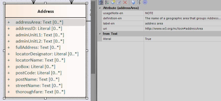
The class Address in Core Location has several properties. All the properties have a displayed name (e.g. "addressArea") with the UML class diagram and associated UML Tags, such as a label for the HTML specification ("address area"), definition, usage note and the related URI.
Case sensitivity and charset
Title: Case sensitivity and charset |
Identifier CMC-R4 |
Statement: All UML Element names are case-sensitive and shall follow the CamelCase convention. |
Description:
The names begin with an upper or lower case letter (A–Z, a–z) for all terms in the model. Digits (0–9) are allowed in the subsequent character positions. [epo-cmc, sec 4.2]
Moreover, we can significantly improve the readability of an ontology if we use consistent capitalisation for concept names; therefore, UML Element names shall be CamelCased [epo-cmc, sec 3.2], [oslo-rules, sec 3.2.20].
The names of
-
UML Classes shall start with an upper-case letter,
-
UML Attributes shall start with a lower-case letter,
-
UML Connectors (including Target Roles and Source Roles) shall start with a lower-case letter.
The names of
-
UML Enumerations, Packages and Datatypes may start with a lower-case or upper-case letter.
Examples:
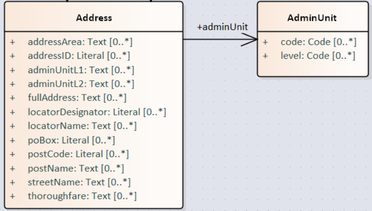
In the image below, there are two classes from Core Location with the related properties and a relation between them. The name of the classes are in UpperCamelCase, the name of the properties are in lowerCamelCase and the relation (adminUnit) is in lowerCamelCase.
Namespaces and prefixes in element names
Title: Namespaces and prefixes in element names |
Identifier CMC-R5 |
Statement: Element names shall be organised by namespaces. Namespaces may be indicated through prefixes delimited by colon (:) character, forming qualified names. |
Description:
To enable the reuse of names defined in other models, and the reuse of unique references for names that support easy identification, namespace management must be considered. We adopt the XML and RDF approach to defining and managing namespaces [xml-ns].
A namespace is a set of symbols that are used to organise objects of various kinds so that these objects may be referred to by name and uniquely identifiable [urn].
A qualified name denotes the URI, which is composed of concatenating the expanded prefix with the local segment [turtle]. A qualified name is a name subject to namespace interpretation [xml-ns]. Syntactically, they are either prefixed names or un-prefixed names. A binding declaration shall be maintained, which binds prefixes to namespace URIs and a default namespace applicable to un-prefixed Element names.
As the Element name is the primary source for deriving URIs, a base URI and a local segment are necessary. The Element name prefix, before the colon, plays the role of namespace name indicating which base URI shall be used, while the Element name, after the colon, is the local segment. See [xml-ns] for more info.
In case the editor decides to omit to specify a prefix in the Element name when a URI generation logic is devised, an implicit prefix can be assumed by default. The qualified names may be structured as follows:
-
prefix:localSegment
-
:localSegment
-
localSegment
Note: The prefixes and namespaces shall be well-defined, maintained, and published as part of the data specification.
Rich annotations through tags
Title: Rich annotations through tags |
Identifier CMC-R6 |
Statement: UML Tags can be conveniently used for annotating the Elements. |
Description:
UML Element tags are key-value pairs that are associated with a UML Element (class, attribute, connector, etc.). The tags can be used as an extension mechanism to the UML language. They can be used to provide information that is not expressible anywhere else on a UML Element.
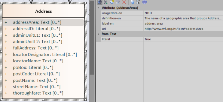
For example, in this style guide, we recommend that the UML Element name shall be used to derive both the concept URI and the concept preferred label. However, if the model editor chooses to use the UML Element name for deriving the concept label alone, then the URI needs to be specified elsewhere. This is one example of how the UML tags can be used: simply specify a new tag, "uri", and provide the concept URI as a value (see figure below).
Another example where tags came in handy is the provisioning of notes of various types. According to the UML standard, UML Elements have only one general description. We recommend using this description solely for definitions. Yet the scope notes, examples, alternative labels, and any other annotations can be provisioned through the UML tagging mechanism (see figure below).
Examples:
Explicit depiction of external dependencies
Title: Explicit depiction of external dependencies |
Identifier CMC-R7 |
Statement: The UML diagrams should depict how the developed model relates to external (reused) models. |
Description:
UML does not support an import mechanism comparable to the one specified in OWL 2. Yet, the reuse of models is a highly encouraged practice. To accommodate such practice, the reused Elements shall be created as in the original model and depicted in diagrams.
The external Elements shall be clearly marked. The easiest way to do so is by providing a namespace prefix. The original meaning shall be preserved without changes to the labels, concept definitions or URIs.
Reused classes shall be depicted in the UML diagrams. Reused properties shall be depicted in diagrams as connectors and attributes. It is not necessary to depict unused classes or properties [oslo-rules, sec 3.1.7].
Examples:
In the example below, a Core Vocabulary Person includes concepts from another vocabulary (FOAF); thus the two classes Person and Agent have the "foaf" namespace prefix specified in front.
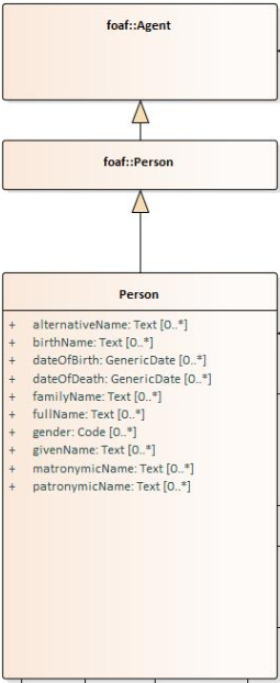
Please note that this is an example of reuse with semantic adaptation. In CPV the Person is more restricted than that in FOAF.
The foaf:Person class represents people. Something is a foaf:Person if it is a person, and it does not matter whether they are alive, dead, real or imaginary. The foaf:Person class is a subclass of the foaf:Agent class, since all people are considered 'agents' in FOAF.
In contrast to that, cpv:Person is defined differently: A individual human being who may be dead or alive, but not imaginary. Hence, the subclass relation.
Class inheritance
Title: Class inheritance |
Identifier CMC-R8 |
Statement: Ensure that the attributes and associations of a superclass apply to all its subclasses. |
Description:
This is a general modelling principle that should be respected, yet when it comes to reusing, such a requirement is often overlooked. This means that the model editor shall carefully analyse the reused model as a whole and how it is integrated with their own model.
Examples:
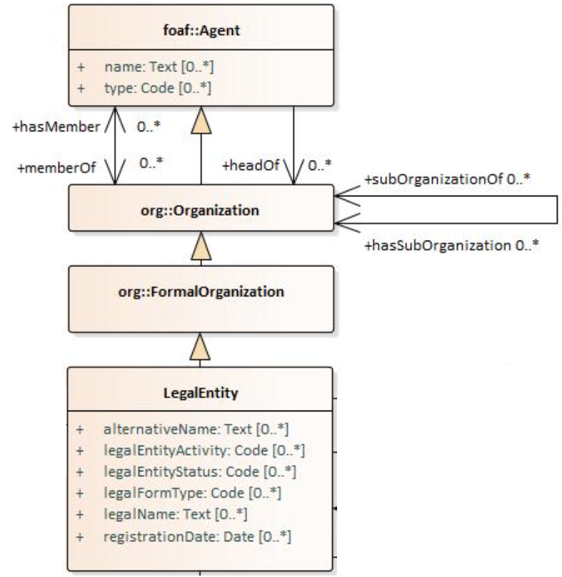
In Core Business Vocabulary, the class LegalEntity is a subclass of org:FormalOrganization from the Organization Ontology (which is a subclass of org:Organization, which is a subclass of foaf:Agent),
and different properties/relations have been inherited such as hasSubOrganization, hasMember, name, type.
See more [oslo-rules sec 3.2.3]
Abstract classes
Title: Abstract classes |
Identifier CMC-R9 |
Statement: Classes that are not intended to be instantiated directly can be marked as abstract. |
Description:
When a (super-)class is created for capturing a level of abstraction in the domain knowledge, it may not always be suitable for instantiation. Editors may choose to mark such classes as abstract and to indicate that their subclasses shall be used in practice. In UML, this can be done via << abstract >> stereotype [see CMC-R17: Using stereotypes].
Attribute definition and usage
Title: Attribute definition and usage |
Identifier CMC-R10 |
Statement: UML Attributes shall be used to define properties taking simple datatype values. An attribute declaration should specify its datatype and multiplicity whenever possible [CMC-R11]. |
Description:
We recommend atomic types are used as attribute types and avoid using another class as the attribute type. Instead, those should be expressed as relationships (represented by Association connectors) between the two classes [CMC-R12].
The reason for this is to keep a clear separation between (a) properties that take a literal value (governed by a datatype, and conceptually corresponding to owl:DatatypeProperty) and (b) properties that take a reference value (governed by a class, corresponding to owl:ObjectProperty). Doing so has two advantages: (a) it confers homogeneity to the model, which enhances readability and decreases ambiguity; (b) the toolchain implementation is easier as there is a clear treatment and interpretation.
literal properties (expressed as attributes datatypes) and relations between two classes (expressed as association connectors). The advantage of
In case of primitive datatypes, high preference shall be given to using OWL 2 compliant XSD [xsd] and RDF [rdf] standard datatypes. For more detailed recommendations on the use of primitive datatypes see convention [CMC-R18].
Properties whose values come from a controlled vocabulary or authority table constitute a special case, because two modelling practices are recognised here: (a) as attributes with type "Code", and (b) as dependency relations pointing to a UML Enumeration named after the controlled list.
In the first case, the attribute type "Code" shall be mapped to the skos:Concept class. The advantage of this approach is the compactness of the diagrams, as fewer boxes appear in them. The disadvantage is the omission to specify precisely, which list the property values are restricted to. Arguably, the controlled list can be provided via the additional UML Tags [CMC-R6], but that value will not be visible in the diagrams.
In the second case, the property is modelled not as an attribute but by using a UML Dependency connector between the UML Class, and the UML Enumeration representing the controlled list, oriented from the Class towards the Enumeration. It denotes that the OWL 2 class has an owl:ObjectProperty whose range is of type skos:Concept and is limited to values of the specified controlled vocabulary. The connector must have a "Source→Target" direction. No other directions are acceptable, and a valid target role name and multiplicity shall be provided [CMC-R14].
Finally, we emphasise that UML Connectors are reserved for the object properties only. Hence, none shall be established between a UML Class element and a UML Datatype element.
Examples:
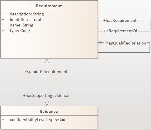
Here we provide an example for the two approaches of specifying attribute datatypes described above. In the CCCEV specification, the class attributes of the Requirement and Evidence classes use loose UML and other datatypes: String, Literal, and Code. No precise definition of what they mean is provided.
The attributes are left underspecified, and with generic datatypes: the description attribute is a generic String, while the type and confidentialityLevelType attributes are specified as Code (without explicitly indicating what this datatype means).
It is also not clear what would be the difference between Literal and String, although one might gain an intuition from the attribute names.
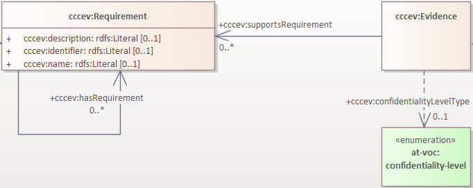
The same classes are reused in the ePO ontology, where the cccev:Requirement and cccev:Evidence class attributes explicitly specify standard datatypes and cardinalities.
Additionally, the cccev:confidentialityLevelType attribute, and also the cccev:type attribute, although not depicted in the screenshot, indicated in the original specification, were converted to dependency connectors, because they are not using an atomic datatype, but rather a controlled list of skos:Concept(s) coming from controlled vocabularies, such as at-voc:confidentiality-level.
Multiplicity of attributes and connectors
Title: Multiplicity of attributes and connectors |
Identifier CMC-R11 |
Statement: The multiplicity of connectors and class attributes should be specified, indicating the minimum and maximum cardinality. The cardinality shall be as permissive as possible in Core Vocabularies and as restrictive as necessary in Application Profiles. |
Description:
If the UML model is developed to represent a Core Vocabulary, then the property cardinality (both UML Attributes and UML
Association) shall be as permissive as possible, for example, [0..*], meaning any occurrence is allowed.
If a structural feature (attribute or association) is irrelevant for the domain or the applications, instead of setting a lower limit of multiplicity to 0, simply remove it from the model [oslo-rules, sec 3.2.15].
However, in the UML models representing Application Profiles, special attention shall be given to the multiplicity, reducing
variation in the instance data to a minimum. And if a property (attribute or connector) is mandatory in the data, then its
minimum cardinality shall be set to 1, for example [1..*] [epo-cmc, sec 4.5].
A good practice is to always indicate cardinality. It may be left unspecified, but this is not recommended. When in doubt,
it is recommended to fall back on the implicit assumption of [0..*]. Not to be confused with the default cardinality assumed
in tools. For example, Enterprise Architect by default assumes [1..1] cardinality for attributes and omits to display it; and a
similar default assumption exists in XML/XSD.
Notation for multiple cardinality can be either with * or n. In principle using either notation is fine, however, it is
recommended to use only one of those notations within a given data specification consistently, if possible, to enhance readability.
It is worth highlighting this, as some UML tools, by default, might use a different notation for multiple cardinality depending
on whether it is specifying the cardinality of attributes vs. that of connectors. The UML processing tools should be implemented so as to handle either of those notations, as their meaning is identical.
Unless, well explained, no rigid constraints shall be imposed on attributes and associations. In other words, if specified, the cardinality shall be the most permissive, where possible [oslo-rules, sec 3.2.15].
Limit the constraints to business rules, do not add technical constraints to the model [oslo-rules, sec 3.2.16].
If an attribute or an association from a reused vocabulary is irrelevant, do not set the lower limit of multiplicity to 0, but simply omit it in the model [oslo-rules, sec 3.2.15].
Examples:
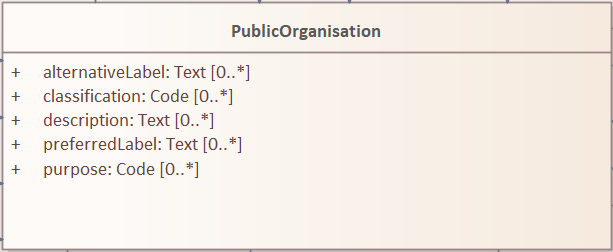
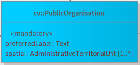
All Core Vocabularies have set a permissive cardinality [0..*], for example, all the properties of Public Organisation, shown with ligh orange background, have multiplicity [0..*], while the same Public Organisation reused in CPSV-AP, shown in blue, has mandatory properties:
Connector definition and usage
Title: Connector definition and usage |
Identifier CMC-R12 |
Statement: UML Connectors shall be used to define relations and properties taking non-atomic type values. A connector declaration should specify multiplicity whenever possible [CMC-R11]. |
Description:
UML Connectors shall be used to denote object properties (see OWL 2 semantics, [owl2]).
First, we explain how the connectors ought to be used, i.e., where to specify the relationship names and multiplicity. Then we explain the optional usage of the dependency connector type.
On connector names, a generic UML connector may have a name applied to it, and it may have source/target roles specified in addition. This provides flexibility to how the domain knowledge may be expressed in UML; however, this freedom increases the level of ambiguity as well. Therefore, we foresee two distinct ways to express properties: using the connector (generic) name or using the connector source/target ends.
We strongly recommend using the source/target role name to indicate the relation name and leave empty the (generic) element name. So, if a target role is specified, then no connector name can be specified. Optionally a source role may be provided to indicate the inverse relation. In this case, the relation direction must be changed from "Source → Target" to "Bidirectional".
Or conversely, if the connector direction is "Bidirectional", then source and target roles must be provided. No other directions are permitted.
It is recommended that each association has a definition. The definition is then used for each role as they represent the same meaning manifested in the inverse direction. Alternatively, definitions can be specified along the target and source roles.
UML defines multiple types of connectors. We recommend relying mainly on the UML Association connector type. Optionally a UML Dependency Connector type may be used if the meaning and usage conditions are well-defined.
The UML Association connectors represent relations between a source and a target classes. The association connector cannot be used between other kinds of UML Elements.
The UML Dependency connector may be used between a UML Class and UML Enumeration boxes, oriented from the Class towards the Enumeration. It indicates the class has an owl:ObjectProperty, whose range is a controlled vocabulary
[CMC-R14]. The connector must have the direction "Source → Target".
No other directions are acceptable.
The UML Generalization connector signifies a class-subClass relation and is transformed into rdfs:subClassOf relation standing between a source and target classes. The connector must have no name or source/target roles specified in the UML model. If a model class should inherit a class from an external model, then proxies must be created for those classes
[GC-R1,
Reuse of a class with semantic adaptation].
For example, if Person specialises a foaf:Agent.
All elements are "public"
Title: All elements are "public" |
Identifier CMC-R13 |
Statement: The visibility of all UML Elements should be "public". |
Description:
For semantic data specifications, accessibility to the information is not a concern. The sole concern is to specify the semantics of the information as precisely as possible. Therefore, the UML access or privacy annotations shall not be interpreted, and the "+" symbol shall always be used next to each property. This symbol means "public" [oslo-rules, sec 3.2.22].
Examples:
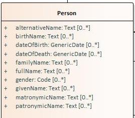
The Person class in Core Vocabulary Person only has public properties indicated with a "+" symbol next to each property.
Controlled lists as Enumerations
Title: Controlled lists as Enumerations |
Identifier CMC-R14 |
Statement: The controlled lists of values shall be referred to as UML Enumerations and specified whenever possible. |
Description:
References to controlled lists shall be done via UML Enumeration elements. Content and lifecycle management of controlled lists shall be separated from the management of the semantic data specification.
Controlled lists play an essential role in establishing interoperability standards. Management and publication of controlled lists are not part of this style guide.
The expectation is that the controlled lists are published in accordance with best practices and represented with the SKOS model using persistent identifiers. In such an approach, the controlled list is expressed as a skos:ConceptScheme and the specific values as skos:Concept(s). Also, such controlled lists are often developed,
published and maintained independently following their own lifecycle, so that they can be reused in other models.
Two use-cases can be identified in practice: (a) when the code list is known and is explicitly referred to as the range of a property, and (b) when a property is modelled but no code list reference is provided as its range.
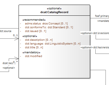
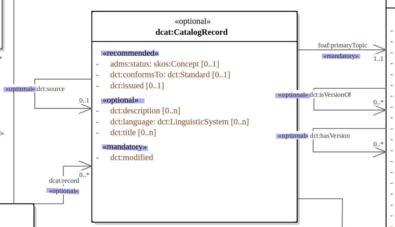
When the authors of a conceptual model intend to omit which controlled list shall be used, then a class attribute with the range skos:Concept (in some cases Code is preferred) can be created to indicate that. This approach can be useful in situations when multiple (external) controlled lists can be used interchangeably. For example, the adms:status property of a dcat:CatalogueRecord shall be a skos:Concept, without specifying the controlled list.
It is advisable, however, to be specific concerning which controlled list shall be used. In such cases, an Enumeration shall be created representing the controlled list. The Enumeration shall be empty, i.e., not specifying any value, because the values are assumed to be maintained externally and only the reference is necessary.
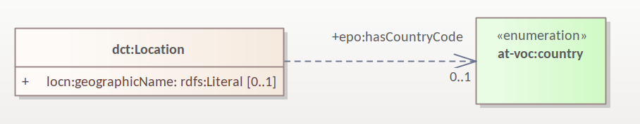
The properties having this controlled list as range shall be depicted as UML connectors (dependencies or associations) between a Class and an Enumeration [CMC-R2]. For example, in ePO, dct:Location can have a country code represented as a dependency relation to at-voc:country (the country authority table published on the EU Vocabularies website).
The name of the Enumeration shall be resolved to a URI identical to that of the skos:ConceptScheme. As for the connector type we recommend using a dependency connector (depicted with a dashed line) because the semantic interpretation differs slightly from the association connector (depicted with a continuous line). Namely, the range of the property has to fulfil two constraints: (a) instantiating the skos:Concept class and (b) being skos:inScheme the intended controlled list [epo-arch].
If the controlled list is specific to the model then the author shall define the values of the UML Enumeration inside of it, which are interpreted as concepts belonging to the containing concept scheme [oslo-rules, sec 3.2.17].
Examples:
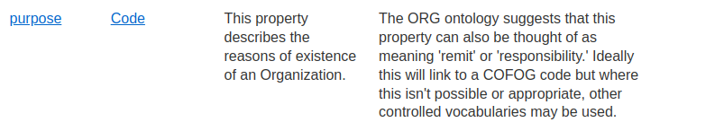
The COFOG controlled list is suggested in Core Public Organisation to describe the purpose of an Organisation (as depicted in the image on top) while in CPSV-AP, the same COFOG list is used to indicate the functions of government which a public service is intended for (as depicted in the image below).
While the COFOG controlled list is owned by the UN and maintained by the Publications Office in the form of SKOS concept schemes, it can be reused by the Core Public Organisation and CPSV-AP independently.
Partition the model into packages
Title: Partition the model into packages |
Identifier CMC-R15 |
Statement: Packages have no semantic value, but shall be used whenever possible to logically organise the model. |
Description:
It is highly recommended to avoid defining any semantic interpretation into UML Packages, as they are best used for organisational purposes, defining logical partitions in the model. Therefore, packages can serve as a method of slicing the conceptual model into subdomains.
It is also possible to use packages as namespace indicators. Although it works well for classes, it fails to cover the needs for managing namespaces of connectors and attributes. Moreover, it does not work in cases when an attribute, or a connector is used multiple times in several packages. Hence, namespace management is easier attained by using other methods such as using prefixes in Element names or using Element tags [epo-cmc, sec 4.3].
Examples:
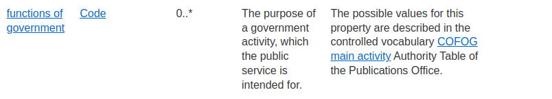
In the image below, each class is organised in a package mapped to a namespace. However, for convenience, Core Vocabularies are in multiple packages but mapped to the same namespace.
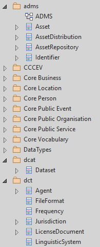
Diagram readability
Title: Diagram readability |
Identifier CMC-R16 |
Statement: UML class diagrams shall be organised for readability. |
Description:
UML class diagrams are used for depicting the conceptual model. Their primary purpose is to construe the meaning of concepts, relations and their organisation to the human reader. Therefore, the diagrams shall be optimised for readability.
We recommend that the diagrams:
-
are well spaced (proper space between lines, boxes and labels)
-
minimise the number of crossing connectors
-
prefer orthogonal to straight connectors
-
align elements horizontally & vertically
-
space elements evenly
-
avoid overlapping labels and depict all labels
-
align labels horizontally and avoid vertical or oblique alignment
-
place subclasses under or to the right of their parent
-
place the part under or to the right of the whole at aggregates or composites .
-
minimise the number of details
-
are short and concise (multiple small(-er) diagrams are preferred to one large diagram)
-
diagram size:
-
prefer multiple themed small(er) diagrams to large and crowded ones
-
diagrams shall not be bigger than one A4 page
-
simplify complex diagrams:
-
by breaking it down into several smaller diagrams
-
by highlighting certain parts of the diagram
-
by hiding attributes, role names, etc. that are not relevant
-
-
-
symbol size:
-
symbols should be equal
-
nothing shall draw more attention unless intended
-
elements of equal importance should be equally large
-
-
inherited attributes of a superclass shall be visible if the superclass is not in the diagram
See also [ oslo-rules, semic-sgdraft ]
Examples:
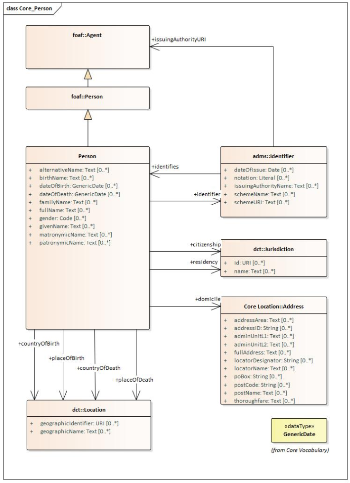
In the example below, taken from Core Person, the classes are aligned vertically and horizontally, subclasses are placed just below the related parent class, the relations are horizontal, vertical, or orthogonal.
Element stereotypes
Title: Element stereotypes |
Identifier CMC-R17 |
Statement: Stereotypes do not have semantic or normative value. They shall be avoided in the conceptual models unless a good motivation, and a strong need is provided. |
Description:
We strongly encourage semantic practitioners to avoid stereotypes of any normative or semantic value. One common usage of stereotypes is to provide deontic indicators. See [GC-7 on Deontic modals] where we explain why their use is discouraged and what can be done instead.
There is a practice to mark some classes as "abstract" with the intention of preventing those from being instantiated. This is also a technical level constraint and does not belong in the semantic layer.
We acknowledge that stereotypes can be useful for editorial and dissemination purposes; to indicate a classification or grouping of a specific sort. Stereotypes can be used to support concerns specific to an implementation of the transformation toolchain. See the examples below.
Examples:
Stereotypes can be used to indicate what content goes into various output file during the transformation process.
Stereotypes can be used to visually group the class attributes. When applied on the relations (UMl connectors) stereotypes have the opposite effect: that of cluttering and decrease the diagram readability.
Datatype definition and usage
Title: Datatype definition and usage |
Identifier CMC-R18 |
Statement: We strongly recommend that only OWL 2 compliant datatypes are used. The creation of custom datatypes shall be avoided. |
Description:
Similar to [epo-cmc, sec 4.7], this convention draws the distinction between primitive (or atomic) types (consisting of single literal value) and composite types (consisting of multiple attributes) (see also [cv-handbook, sec 3.1]). In fact, the composite datatypes must be defined as classes and handled as such. For example, Amount, Identifier, Quantity and Measurement are to be treated as classes, even if conceptually they could be seen as composite datatypes.
It is recommended to employ the primitive datatypes that are already defined in XSD [xsd] and RDF [rdf], in particular a subset of those that is OWL 2 compliant. This should cover the standard, and most common types. Thus, definitions of custom datatypes shall be avoided unless the model really needs them. Such cases are, however, rare.
The reason for avoiding complex datatypes, is that once we start structuring how data shall be organised, besides syntactic definitions, we inevitably embed semantic aspects as well. Doing so, the semantics of the structure is obscured and trapped in a technical interoperability layer. For example, xsd:duration encodes both the amount(s) and unit(s) of time into a regular expression that looks like this <period>P5Y2M10D</period>.
The definition of datatypes in the UML model should be also avoided, even in cases where a toolchain performing the transformation of UML can automatically resolve those into their XSD equivalent using a correspondence table, such as the one presented below.
Note that from the family of string datatypes we recommend using the following ones (in this order of preference): rdf:PlainLiteral, rdfs:Literal, xsd:string, and rdf:langString. Often enabling multilingual data specification is a necessity.
UML |
XSD |
Boolean |
xsd:boolean |
Float |
xsd:float |
Integer |
xsd:integer |
Character, String |
xsd:string / rdf:langString |
Short |
xsd:short |
Long |
xsd:long |
Decimal |
xsd:decimal |
Date |
xsd:date |
DateTime |
xsd:dateTime |
xsd:anyURI |
|
Code |
see CMC-R14 |
We strongly recommended the use of OWL 2 compliant XSD and RDF standard datatypes, if possible. They might be useful also for indicating a specific datatype, which is not possible with the UML ones. For example, making a distinction between a general string (xsd:string) and a literal with a language tag (rdf:langString), or XML encoded ones such as rdf:HTML and rdf:XMLLiteral.
The table above provides a simplified correspondence between UML and XSD datatypes, but for a complete list of available recommended datatypes the standard specifications shall be consulted: