The SEMIC Core Vocabularies Handbook
- 1. Introduction
- 2. Creating a new data model from an existing Core Vocabulary
- 2.1. Create a new XSD schema from a Core Vocabulary (UC1.1)
- 2.2. Create a new JSON-LD context definition from a Core Vocabulary (UC1.2)
- 3. Mapping an existing model to Core Vocabularies
- 3.1. Map an existing conceptual model to a Core Vocabulary (UC2.1)
- 3.1.1. Use case description
- 3.1.2. Guidelines on how to map an existing conceptual model to a Core Vocabulary
- 3.1.3. Tutorial: Map Schema.org to the Core Business Vocabulary
- 3.1.3.1. Phase 1: Staging (Defining the requirements)
- 3.1.3.2. Phase 2: Characterisation (Defining source and target models)
- 3.1.3.3. Phase 3: Reuse of existing mappings
- 3.1.3.4. Phase 4: Matching (execute and filter matching candidates)
- 3.1.3.5. Phase 5: Validate alignments
- 3.1.3.6. Phase 6: Application (operationalise the mappings)
- 3.2. Map an existing XSD Schema to a Core Vocabulary (UC2.2)
- 3.1. Map an existing conceptual model to a Core Vocabulary (UC2.1)
- 4. Concluding remarks
- Appendix: Additional Use Cases
- Glossary
- References
1. Introduction
This Handbook explains the role of Core Vocabularies in enabling semantic interoperability at the EU level and provides a practical guide for public administrations to use them. It is intended for business users who wish to understand how the Core Vocabularies can be useful, and for semantic engineers who seek straightforward guidance for specific use cases.
For first-time readers of this Handbook, we recommend starting with the remainder of this section, where interoperability is introduced, the role of Core Vocabularies is explained, and the important use cases are summarised.
Readers familiar with the SEMIC Core Vocabularies and seeking practical guidance are advised to go directly to the main part of the Handbook, which describes use cases, methodology recommendations, and tutorials for:
-
creating new semantic data specifications or stand-alone data models by using Core Vocabularies, and
-
mapping existing data models to Core Vocabularies.
1.1. Intended audience
This handbook is intended for two main audiences: 1) administrative professionals, including policy officers and possibly also legal experts, and 2) technical experts and IT professionals. Public administrations involve both legal/administrative experts and technical professionals. While they may not always “speak the same language”, they must work together to ensure smooth digital transformation. Semantic interoperability provides the common foundation that allows them to bridge their disciplinary differences and find common ground, enabling effective collaboration and thereby contributing to improved public services. Each intended audience will gain new insights relevant for their respective roles.
Administrative Professionals & Legal Experts
By reading this handbook, domain experts will:
-
Understand the role of semantic interoperability at the EU level, which might also be of use at the national, regional, and local level.
-
Gain insight about how structured data and shared vocabularies enhance legal clarity, data exchange, and cross-border cooperation.
-
Gain insights into how interoperability supports public services and reduces administrative burdens.
It is expected that this will facilitate coordination with technical teams to ensure that interoperability initiatives meet both legal and operational requirements and assist the administrative professionals and legal experts in making informed decisions prioritising IT projects that align with interoperability goals.
Technical Experts & IT Professionals
By engaging with this handbook as both a reference manual and a practical guide, the technical experts and IT professionals who design, implement, and maintain the software ecosystem will:
-
Learn how to design and implement interoperable systems using the Core Vocabularies and semantic data models.
-
Understand methodologies for creating, mapping, and integrating semantic data models in their systems.
-
Be able to apply best practices for data exchange, ensuring consistency and accuracy across different systems.
-
Use standardised approaches to enhance data accessibility, transparency, and reuse in line with FAIR principles [fair].
-
Ensure compliance with the SEMIC Style Guide rules & principles [sem-sg].
It is expected that this will not only facilitate communication with the domain experts, but also further streamline software development conformant to the user specification and, ultimately, the citizens who benefit from more smoothly functioning digital services.
1.2. Structure of the Handbook
The Handbook has two types of content:
-
Explanatory Sections: Intended for administrative professionals and legal experts. They explain interoperability, the role of Core Vocabularies, and describe relevant use cases. It helps non-technical stakeholders understand why semantic interoperability matters and how it supports policy implementation. Each use case is also accompanied by a business case scenario and a user story.
-
Practical Guidance Sections: Designed for technical experts, data architects, and IT professionals, which provide methodologies and step-by-step tutorials for adopting and implementing Core Vocabularies. It includes instructions on creating new semantic data specifications by extending Core Vocabularies, mapping existing data models to them, and ensuring interoperability through standardised practices.
The structure of the main part of the Handbook is as follows. First, the notion of interoperability and the principal use cases will be introduced, which feature the most common, challenging, and interesting scenarios. This is followed by two key chapters, on creating new models and on mapping existing models, which describe and illustrate the principal use cases. For each use case, there is a description intended for administrative professionals and legal experts, guidelines for implementation that describe procedures how to accomplish the goal of the use case, which are then demonstrated in the tutorial for the use case. The guidelines and tutorials are aimed at the technical experts.
Finally, the appendix contains a glossary of terms, additional use cases not covered in this handbook, and the references.
1.3. Interoperability and Core Vocabularies
This section introduces what interoperability is, what makes it semantic, and how Core Vocabularies–which is where key concepts are specified in human-readable and machine-processable formats–contribute to it.
Sharing data easily is indispensable for effective and efficient public services. Sharing may be done through offering one point of access, and often involves reusing the data in multiple applications across multiple departments and organisations. To make this work, the information systems need to be interoperable.
1.3.1. What is interoperability?
Following the European Interoperability Framework (EIF) [eif], interoperability is defined as “the ability of organisations to interact towards mutually beneficial goals, involving the sharing of information and knowledge between these organisations, through the business processes they support, by means of the exchange of data between their ICT systems”, where, for the purpose of EIF, ‘organisations’ refers to “public administration units or any entity acting on their behalf, or EU institutions or bodies”. It is what “enables administrations to cooperate and make public services function across borders, across sectors and across organisational boundaries”, including enabling “public sector actors to connect, cooperate and exchange data while safeguarding sovereignty and subsidiarity”, as described in the EC communication accompanying the Interoperable Europe Act [int-eu].
Existing acts and frameworks related to interoperability
The European Union has formulated Acts, regulations, and frameworks that intend to foster achieving that, including the Data Act [data-act], Data Governance Act [dga], the European Interoperability Framework (EIF) [eif], and the Interoperable Europe Act [iea24], which underscore the importance of harmonised data practices across member states. These Acts and frameworks emphasise that true interoperability goes far beyond just connecting systems at a technical level.
The EU Data Act is a legislative framework aimed at enhancing the EU’s data economy by improving access to data for individuals and businesses. It entered into force on January 11, 2024, and is designed to ensure fairness in data allocation and encourage data-driven innovation.
The Data Governance Act (DGA) is a regulation by the European Union aimed at facilitating data sharing and increasing trust in data usage. It establishes a framework for the reuse of publicly held data and encourages the sharing of data for altruistic purposes, while also regulating data intermediaries to enhance data availability and overcome technical barriers. The act is part of the broader European strategy for data, which seeks to create a more integrated and efficient data economy.
The EIF provides specific guidance on how to set up interoperable digital public services. It gives guidance, through a set of recommendations, to public administrations on how to improve governance of their interoperability activities, establish cross-organisational relationships, streamline processes supporting end-to-end digital services, and ensure that existing and new legislation do not compromise interoperability efforts.
The Interoperable Europe Act, which entered into force on 11 April 2024, aims to enhance cross-border interoperability and cooperation in the public sector across the EU. It is designed to support the objectives of the Digital Decade, ensuring that 100% of key public services are available online by 2030, including those requiring cross-border data exchange. The Act addresses challenges by creating tools for interoperability within public administrations and removing legal, organizational, and technical obstacles. It envisions an emerging ‘network of networks’ of largely sovereign actors at all levels of government, each with their own legal framework and mandates, yet all interconnected”, i.e., for seamless cross-border cooperation, which is to be supported by mandatory assessments.
1.3.2. What is semantic interoperability and how to achieve it?
While data exchange is an obvious requirement for interoperability, there are fine but crucial distinctions between data format, syntactic, and semantic interoperability. A standardised syntax and data format to store data lets one exchange data, such as creating an SQL database dump in one tool and seamlessly reopening it in another relational database management system, or lets one send and receive emails that arrive properly in each other’s inbox.
Interoperability at the semantic level concerns the meaning of that data. One may have the same format and language to represent data, such as XML, but with a tag <bank> … </bank>, neither the software nor the humans can determine from just that what sort of bank is enclosed within the tags. Such meaning is defined in various artefacts such as vocabularies, thesauri, and ontologies. A <fin:bank> tag in a document may then be an implemented version of its definition at the semantic layer, where the entity has a definition and a number of properties specified in the model (abbreviated with fin), like that the fin:bank is a type of financial organisation with a board of directors and has a location for its headquarters. This enables not only correct sending and receiving of data, but also exchanging data reliably, accessing the right data when querying for information, obtaining relevant data in the query answer, and merging data.
Interoperability thus consists of a semantic component as well, which "refers to the meaning of data elements and the relationship between them" and "includes developing vocabularies and schemata to describe data exchanges" [eif4scc]. According to the EIF, section 3.5 [eif2], semantic interoperability "ensures that the precise format and meaning of exchanged data and information is preserved and understood throughout exchanges between parties, in other words ‘what is sent is what is understood’." One recommended way to achieve semantic interoperability between public administrations is to use semantic assets, such as semantic data models, information models, ontologies, and vocabularies. SEMIC uses models called Core Vocabularies.
1.3.3. What is a Core Vocabulary?
A Core Vocabulary (CV) is a basic, reusable, and extensible specification that captures the relevant characteristics of entities, which can be used to add semantics to data and information in a context-neutral manner [cv-hb]. Its primary purpose is to provide standardised terms that can be reused across various application domains, typically realised as a lightweight ontology (optionally accompanied by a permissive data shape) and documented in a concise specification. Core Vocabularies for SEMIC [sem-sg-cvs] are maintained by the SEMIC action under the Interoperable Europe umbrella of DG DIGIT and are described in the SEMIC Core Vocabularies section below.
1.3.4. SEMIC Core Vocabularies
Since 2011, the European Commission has facilitated international working groups to forge consensus and maintain the SEMIC Core Vocabularies. A short description of these vocabularies is included in the Table below. The latest release of the SEMIC Core Vocabularies can be retrieved via the SEMIC Support Center [semic] or directly from the GitHub repository [semic-gh] in both human- and machine-readable formats. They are published under the CC-BY 4.0 licence [cc-by]. Henceforth, when we use the term Core Vocabularies, we refer to the SEMIC Core Vocabularies specifically.
| Vocabulary | Description |
|---|---|

|
The Core Person Vocabulary (CPV) [cpv] is a simplified, reusable and extensible vocabulary that captures the fundamental characteristics of a person; e.g., the name, gender, date of birth, and location. This specification enables interoperability among registers and any other ICT-based solutions exchanging and processing person-related information. |

|
The Core Business Vocabulary (CBV) [cbv] is a simplified, reusable and extensible vocabulary that captures the fundamental characteristics of a legal entity; e.g., the legal name, activity, and address. The Core Business Vocabulary includes a minimal number of classes and properties modelled to capture the typical details recorded by business registers. It facilitates information exchange between business registers despite differences in what they record and publish. |

|
The Core Location Vocabulary (CLV) [clv] is a simplified, reusable and extensible vocabulary that captures the fundamental characteristics of a location, represented as an address, a geographic name, or a geometry. The Location Core Vocabulary provides a minimum set of classes and properties for describing a location represented as an address, a geographic name, or a geometry. This specification enables interoperability among land registers and any other ICT-based solutions exchanging and processing location information. |

|
The Core Criterion and Core Evidence Vocabulary (CCCEV) [cccev] supports the exchange of information between organisations that define criteria and organisations that respond to these criteria by means of evidence. The CCCEV addresses specific needs of businesses, public administrations and citizens across the EU, including the following use cases:
|

|
The Core Public Organisation Vocabulary (CPOV) [cpov] provides a vocabulary for describing public organisations in the European Union. It addresses specific needs of businesses, public administrations and citizens across the European Union, including the following use cases:
|

|
The Core Public Event Vocabulary (CPEV) [cpov] is a simplified, reusable and extensible vocabulary that captures the fundamental characteristics of a public event, e.g., the title, the date, the location, the organiser etc. It aspires to become a common model for describing public events (conferences, summits, etc.) in the European Union. This specification enables interoperability among registers and any other ICT based solutions exchanging and processing information related to public events. |

|
The Core Public Service Vocabulary Application Profile (CPSV-AP) [CPSV-AP] is a vocabulary for describing public services and the associated life and business events. With the CPSV-AP it is possible to:
|
The Core Vocabularies are semantic data specifications [sem-sg-wsds] that are disseminated as the following artefacts:
-
lightweight ontology [sem-sg-wio] for vocabulary definition expressed in OWL [owl2];
-
loose data shape specification [sem-sg-wds] expressed in [shacl];
-
human-readable reference documentation [sem-sg-wdsd] in HTML (based on ReSpec [respec]);
-
conceptual model specification [sem-sg-wcm] expressed in UML Class Diagram notation [uml].
1.3.5. Why Core Vocabularies?
Modern-day information system design has moved the goalposts, notably that they typically have to operate in an ecosystem of tools and data, which caused a number of new problems, notably:
-
Developers are reinventing the wheel by modelling the same topics over and over again in different organisations, which is a wasteful use of time and other resources.
-
Consequent near-duplications and genuine differences cause, at best, delays in interoperability across systems and, at worst, legally inconsistent data, thereby harming individuals or organisations.
-
A lack of a high-level common vocabulary causes engineers to create many 1:1 low-level technical mappings between resources that are buried in implementations, which become an unmaintainable mesh structure the more new resources are added and the more often the sources are updated.
-
Individual formats of published datasets require more ad hoc Extract-Transform-Load scripts to reuse commonly reused data, such as cadaster data and registries of companies, imposing a higher burden on tool developers to create and maintain the data processing scripts.
Core vocabularies contribute to the solution of all these problems at once thanks to providing agreed-upon shared common building blocks in commonly used domains, such as public services, events, persons and more. Core Vocabularies can be used as, as formulated on the SEMIC Support Centre site:
-
a starting point for designing the conceptual data models and application profiles for newly developed information systems, simply through reuse of the terminology;
-
the basis of a particular data model that is used to exchange data among existing information systems;
-
common model to integrate data originating from disparate data sources thanks to the shared terminology;
-
the foundation for defining a common export format for data and thereby facilitating the development of common import mechanisms.
Concretely, let us illustrate the problem versus the solution for languages designed for interoperability, such as XML. The XSD schema and the corresponding XML files that adhere to it help achieve syntactic interoperability for those XML files. It does not achieve interoperability among the XSD schemas, however, because there is no such mechanism to declare that a tag in schema xs1, say, <bank> is the same as <bank> in schema xs2. We need another mechanism to achieve that, which is provided by vocabularies that operate at a higher level of abstraction to which the XSD schemas can be linked: the semantic layer.
Alternatively, one can avoid the interoperability problem by creating multiple XSD schemas from the same vocabulary which then offers semantic interoperability implicitly. When a developer wants to reuse a Core Vocabulary-based XSD, they only can be used as-is or extended into a more specific application profile, but not modified to the extent that it could to contradict the Core Vocabulary, thereby continuing to foster the intended interoperability.
In addition, with Core Vocabularies represented in RDFS or OWL, one can mix vocabularies and link to external concepts, whereas that is not possible with XSD where only types and elements defined in the single schema can be used.
Finally, an added benefit is that while multilingual XSD is possible through manually created tags to store the multilingual information, such features are already part of standardised vocabulary languages used by the Core Vocabularies, such as SKOS, RDF, RDFS, and OWL, thereby offering a standardised approach to multilingual labels, which facilitates software development, reuse, and interoperability.
Core Vocabularies lifecycle
The SEMIC Core Vocabularies have been developed following the ‘Process and methodology for developing Core Vocabularies’ [cv-met] of which the most relevant section is depicted in the figure below. Assuming stakeholders and Working Group members with relevant roles are in place, requirements are defined, which are thoroughly assessed on existing standardisation efforts, evidence, and other data models. When a change is deemed necessary, it enters a drafting phase that focuses on the technical details whilst adhering to the SEMIC Style Guide, followed by public consultations. Thereafter, if deemed necessary based on the feedback, it will undergo another modelling iteration, else the changes are refined and the model finalised. The final model is formally approved, implemented, and documented, ensuring they are well-understood and agreed upon by all relevant parties.
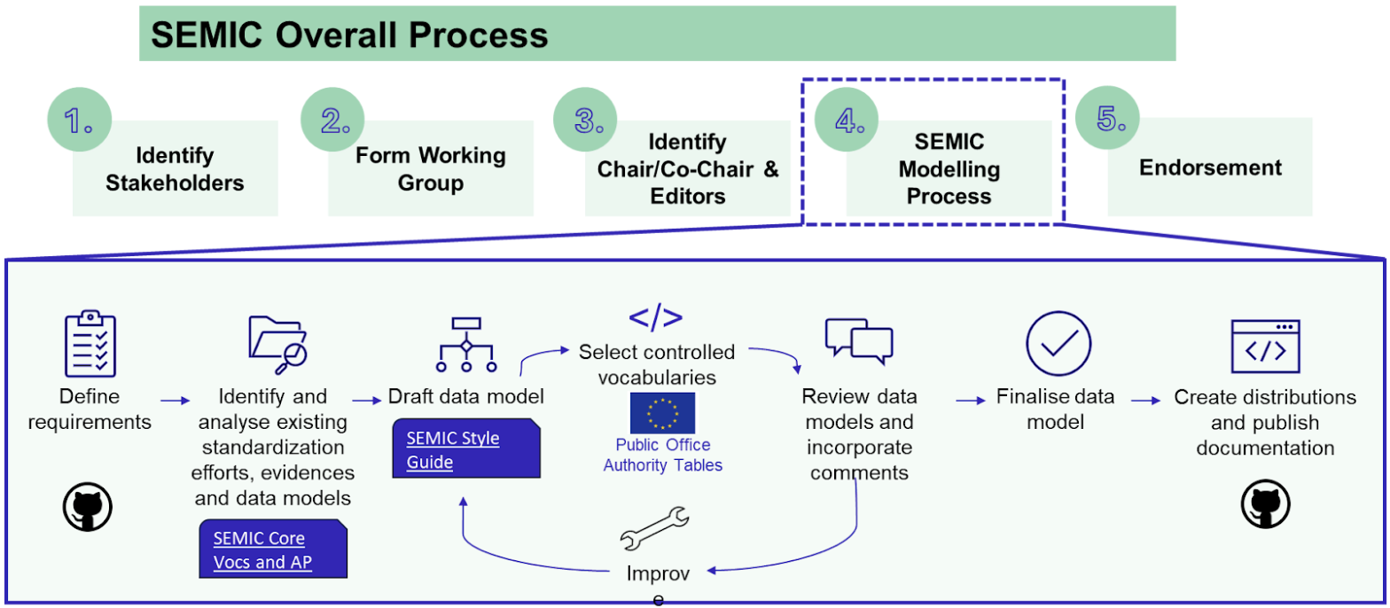
The release management of Core Vocabularies follows a structured timeline for all tasks and each release includes detailed documentation to support implementation, so that users can integrate new versions with minimal disruption. This process maintains the quality and relevance of the Core Vocabularies, and supports a dynamic and responsive framework for semantic interoperability within digital public services.
1.4. Overview of use cases for using Core Vocabularies
Let us commence with a practical example that contributes to setting the stage for defining the use cases afterward.
1.4.1. A practical example
Imagine you are starting a business in another EU country. To complete the registration, you need to submit a criminal record certificate and a diploma certificate to multiple public organisations. In many countries, this process is still manual—people must physically visit different ministries, request documents, and submit them in person or via email. Each organisation may use different formats and terminology, making it difficult for institutions to interpret and process the information correctly. This can generate mistakes during data entry due to terminological confusion that subsequently have to be corrected. Without a common reference vocabulary, these organisations interpret the data differently, making seamless exchange impossible.
Now, imagine an alternative scenario, such as indicated by the Once-Only Technical System (OOTS) [oots] for the Single Digital Gateway Regulation [sdgr], where this entire process is fully automated. Instead of individuals having to visit multiple offices, the ministries and public administrations would communicate directly with each other, exchanging the necessary information in a structured and consistent manner. The citizen could simply grant approval to the administration office to fetch the data from their home country that already had recorded the relevant data. This would eliminate the need for data re-submission by citizens (according to the once-only principle) and for duplicate document submissions, as well as avoid possible data entry issues and thereby making evidence verification faster. Overall, achieving this degree of data interoperability can considerably reduce burdens for citizens and public administrations in terms of hassle, costs, and mobility.
Defining the what is one step; the how to achieve it is another.
1.4.2. How to solve the scenario with semantic data specifications
How can different systems and institutions "talk" to each other effectively at the level of software applications and the various types of databases? That technical level uses data models to structure the stored data. This first raises the questions of who is developing those data models, and how, and then how those different data models across the database and applications agree on the terminology used in them. Therefore, the challenge is not only technical but also semantic. It is not enough for systems to simply exchange data—they must also be able to interpret the meaning behind the data in a consistent way such that it will not result in errors or so-called 'dirty' (incorrect or incomplete) data. This requires a common language and a (multilingual) structured vocabulary at both the business process level and the IT systems level.
This is where standards to declare the semantics play a crucial role. By using Core Vocabularies, public administrations can ensure that data and information are structured in a way understood by both humans and machines. Standardised models allow different organisations to recognise and process information without discrepancies, thereby reducing errors and the need for manual intervention. As a result, governments can facilitate seamless data exchange, ensuring that information is accurately expressed, shared, interpreted, and processed across systems, leading to more efficient approvals and interactions for businesses, governmental organisations, and citizens.
These vocabularies can then be used by the IT personnel of the various departments to create their data models, thereby in effect avoiding incompatibility by building interoperability into the systems from the start. But what about existing systems from, e.g., a Ministry of Economic Affairs, a national Chamber of Commerce, and other organisations that are relevant to the Single Digital Gateway? Setting aside existing systems to build a new one may not be reasonable and cost effective, especially when they already have their own entrenched terminologies embedded into them or have already incorporated other models used internationally, such as Schema.org or the Financial Business Industry Ontology. There is a solution to that problem, too: map the specifications at this semantic layer to make the other model interoperable with the CV and then use both through that declared mapping ‘bridge’ between them.
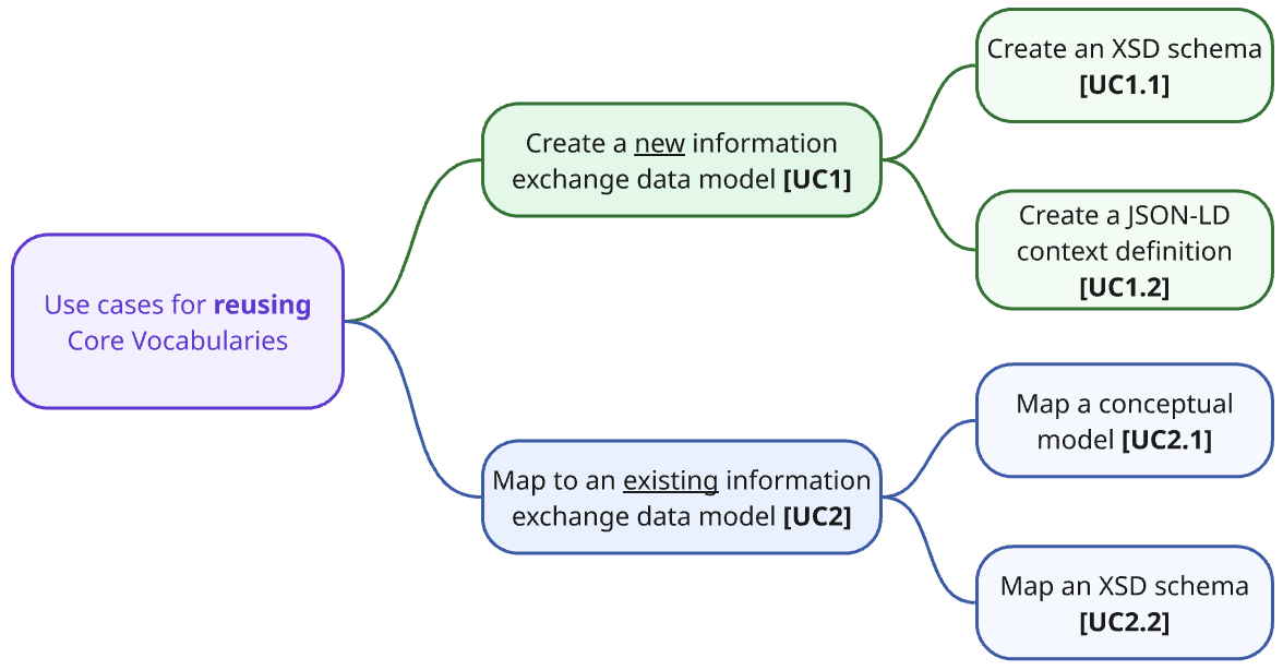
It is these two key ways of using CVs that will be covered in the use cases: creating new data specifications availing of the CVs (possibly adding one’s own additional content to it) and mapping existing schemas.
1.4.3. Introduction to the use cases covered in the handbook
This handbook serves as a practical guide for using Core Vocabularies in various common situations. To provide clear and actionable insights, we have categorised potential use cases into two groups:
-
Primary Business and Technical Use Cases: These are the most common, interesting, and/or challenging scenarios, all thoroughly covered within this handbook.
-
Additional Business and Technical Use Cases: These briefly introduce other relevant scenarios but are not elaborated on in detail in this handbook.
A business case in the current context is to be understood as a narrative user story (in terms of the technical expert terminology), which functions as motivation for the use case. They capture the who, what, and why in a broader context, including who the beneficiary of an action is, what they need, and what the benefit of it is. Such a narrative is then structured into a user story as a structured sentence that captures the essence of the business case yet also communicates genericity. For the technical reader, a use case specification is listed afterwards, which provides a schematic view as a step towards the precise technical specifications.
We differentiate between use cases focussed on the creation of new artefacts and those involving the mapping of existing artefacts to Core Vocabularies. For better clarity, we numbered the use cases and organised them into two diagrams, one for the primary scenarios (see Figure 2, below) and the other for depicting the additional ones. The former are addressed in the main part of this handbook, whereas the latter are listed in the Appendix and may be elaborated on at a later date if there is a demand from the community.
The use cases are written in white-box point of style oriented towards user goals following Cockburn’s classification [uc-book]. We will use the following template to describe the relevant use cases:
Use Case <UC>: Title of the use case |
Goal: A succinct sentence describing the goal of the use case |
Primary Actor: The primary actor or actors of this use case |
Actors: (Optional) Other actors involved in the use case |
Description: Short description of the use case providing relevant information for its understanding |
Example: An example to illustrate the application of this use case |
Note: (Optional) notes about this use case, especially related to its coverage in this handbook |
The use cases described below serve as a quick-access overview; complete concrete scenarios are introduced in the respective dedicated section’s “Description” section.
UC1: Create a new model from a Core Vocabulary
For creating new models, there are two business cases for illustration. In short:
-
UC1.1: Jean-Luc from the Maltese Chamber of Commerce who wants to create an XML schema (XSD) by using the Core Business Vocabulary (CBV), so that he reduces design time and ensures consistent, interoperable, and standards-compliant e-form validation across government systems.
-
UC1.2: Nora from the Norwegian Digitalisation Task Force who needs to provide guidance to the City of Oslo to create a new JSON-LD context based on the Core Public Services Vocabulary Application profile (CPSV-AP). This way, the City can create smart data models compliant with national and European interoperability standards and publish linked data for cross-system data exchange.
The main use case UC1 is summarised as follows, which is subsequently refined into two more specific cases.
Use Case UC1: Create a new information exchange data model |
Goal: Create a new standalone data schema that uses terms from Core Vocabularies. |
Primary Actors: Semantic Engineer, Software Engineer |
Description: The goal is to design and create a new data schema or information exchange data model that is not part of a more comprehensive semantic data specification, relying on terms from existing CVs as much as possible. |
Note: As this is a more generic use case it will be broken down into concrete use cases that focus on specific data formats. |
Use Case UC1.1: Create a new XSD schema |
Goal: Create a new standalone XSD schema that uses terms from Core Vocabularies. |
Primary Actors: Semantic Engineer, Software Engineer |
Description: The goal is to design and create a new XSD schema that is not part of a more comprehensive semantic data specification, relying on terms from existing CVs as much as possible. As an information exchange data model, an XSD schema can be used to create and validate XML data to be exchanged between information systems. |
Example: OOTS XML schema mappings [oots] |
Note: A detailed methodology to be applied for this use case will be provided in the Create a new XSD schema section. |
Use Case UC1.2: Create a new JSON-LD context definition |
Goal: Create a new standalone JSON-LD context definition that uses terms from Core Vocabularies. |
Primary Actors: Semantic Engineer, Software Engineer |
Description: The goal is to design and create a new JSON-LD context definition that is not part of a more comprehensive semantic data specification, relying on terms from existing CVs as much as possible. As an information exchange data model, a JSON-LD context definition can be integrated in describing data, building APIs, and other operations involved in information exchange. |
Example: Core Person Vocabulary [cpv-json-ld], Core Business Vocabulary [cbv-json-ld] |
Note: A detailed methodology to be applied for use cases will be provided in the Create a new JSON-LD context definition section. |
UC2: Map an existing model to a Core Vocabulary
For mapping vocabularies, there are two business cases for illustration. In short:
-
UC2.1: Sofía with the Department of Agriculture’s outreach division wants to map her existing conceptual model about outreach events that already uses the Core Business Vocabulary (CBV) and align it with Schema.org. This way, the event data can be distributed across the interoperable Europe and global web vocabularies, enabling a wider reach of accurate data exchange.
-
UC2.2.: Ella, working for the National Registry of Certified Legal Practitioners, wants to map her existing XML Schema Definition (XSD) to the Core Business Vocabulary (CBV). This enables her to transform the XML data into semantically enriched RDF such that it complies with European interoperability standards and supports linked data publication, and thereby enabling cross-system data exchange.
The main use case UC2 is summarised as follows, which is subsequently refined into two specific ones. They serve as a quick overview; concrete scenarios are introduced in the dedicated “Description” section.
Use Case UC2: Map an existing data model to a Core Vocabulary |
Goal: Create a mapping of an existing (information exchange) data model, to terms from Core Vocabularies. |
Primary Actors: Semantic Engineer |
Actors: Domain Expert, Software Engineer |
Description: The goal is to design and create a mapping of an ontology, vocabulary, or some kind of data schema or information exchange data model that is not part of a more comprehensive semantic data specification, to terms from CVs. Such a mapping can be done at a conceptual level, or formally, e.g., in the form of transformation rules, and most often will include both. |
Note: Since this is a more generic use case it will be broken down into concrete use cases that focus on specific data models and/or data formats. Some of those use cases will be described in detail below, while others will be included in the Appendix with the additional use cases. |
Use Case UC2.1: Map an existing Ontology to a Core Vocabulary |
Goal: Create a mapping between the terms of an existing ontology and the terms of Core Vocabularies. |
Primary Actors: Semantic Engineer |
Actors: Domain Expert, Business Analyst, Software Engineer |
Description: The goal is to create a formal mapping expressed in Semantic Web terminology (for example using rdfs:subClassOf, rdfs:subPropertyOf, owl:equivalentClass, owl:equivalentProperty, owl:sameAs properties), associating the terms in an existing ontology that defines relevant concepts in a given domain, to terms defined in one or more CVs. This activity is usually performed by a semantic engineer based on input received from domain experts and/or business analysts, who can assist with the creation of a conceptual mapping. The conceptual mapping associates the terms in an existing ontology, which defines relevant concepts within a specific domain, to terms defined in one or more SEMIC Core Vocabularies. The result of the formal mapping can be used later by software engineers to build information exchange systems. |
Example: Mapping Core Person to Schema.org [map-cp2org], Core Business to Schema.org [map-cb2org], etc. |
Note: A detailed methodology to be applied for this use case will be provided in the Map an existing Model section. |
Use Case UC2.2: Map an existing XSD schema to a Core Vocabulary |
Goal: Define the data transformation rules for the mapping of an XSD schema to terms from Core Vocabularies. Create a mapping of XML data that conforms to an existing XSD schema to an RDF representation that conforms to a Core Vocabulary for formal data transformation. |
Primary Actors: Semantic Engineer |
Actors: Domain Expert, Business Analyst, Software Engineer |
Description: The goal is to create a formal mapping using Semantic Web technologies (e.g. RML or other languages), to allow automated translation of XML data conforming to a certain XSD schema, to RDF data expressed in terms defined in one or more SEMIC Core Vocabularies. This use case required definitions of an Application Profile for a Core Vocabulary because the CV alone does not specify sufficient instantiation constraints to be precisely mappable. |
Example: ISA2core SAWSDL mapping [isa2-map] |
Note: A detailed methodology to be applied for this use case will be provided in the Map an existing XSD schema section. |
The additional use cases are described in the Appendix.
2. Creating a new data model from an existing Core Vocabulary
Technologies rise and decline in popularity, yet one of the red threads through the computational techniques over the decades is the management of structured data. Data needs to be stored, processed, acted upon, shared, integrated, presented, and more, all mediated by software. This also means that the structure of the data needs to be machine-readable far beyond the simple scanned hard-copy administrative forms or legal documents. Structured data mediates between entities in the real world and their representation in the software.
For instance, to represent the fact “govtDep#1 subcontracts comp#2”, we might have
-
a table with government departments that also contains a row with govtDep#1;
-
a table with companies and their identifying data including comp#2; and
-
a table with subcontracting relationships between instances, including (GovtDep#1,Comp#2).
A mechanism to capture the sort of structured and semi-structured data which may be stored and managed in the system is called a data model at the level of the technical implementation and conceptual data model or vocabulary as part of a semantic data specification when it is implementation-independent. Such models represent the entity types, such as GovernmentDepartment, Company, and its more generic type Organisation from our example, along with relationships between entity types, such as Subcontracting. Data models typically also implement business rules or constraints that apply to the particular organisation. For instance, one rule might state that each government department is permitted to subcontract at most 15 companies in country#3 whereas there may be no upper bound to subcontracting in country#4 and a prohibition on subcontracting (i.e., is permitted to subcontract at most 0) in country#5. These variations require different data models or application profiles, although they may use the same vocabulary.
This raises a number of questions:
-
What sort of data models are there?
-
Who develops those models?
-
How do they develop the models?
-
How can we ensure that those models are interoperable across applications and organisations, so that the data is interoperable as a consequence of adhering to those model specifications?
There are a number of languages to declare data models, which are normally developed by data modellers and database designers. While they may develop a data model from scratch, increasingly, they try to reuse existing specifications to speed up the development and foster interoperability. For use case 1, we address these questions from the perspective of creating new data models that reuse Core Vocabularies, either in full or in part, depending on the specific needs. In this chapter we focus on creating two types of data models: XSD schemas and JSON-LD contexts.
Each model type has its business case providing a rationale why one would want to do this, which is described in the respective “Use case description” sections. The respective “Guidelines” sections then walk the reader through the creation process (addressing mixed technical and non-technical audience), and finally the respective “Tutorial” sections target technical staff with a step-by-step example that implements the guideline.
2.1. Create a new XSD schema from a Core Vocabulary (UC1.1)
2.1.1. Use case description
We will introduce the motivation for the use case with a user story.
Imagine Jean-Luc, a semantic/software engineer assigned to develop a software application for processing online forms for the Maltese Chamber of Commerce. Among the format options of online forms are Office365, CSV, and XML that each have their pros and cons. Jean-Luc chooses XML, since many other forms are already being stored in XML format.
He is aware that XML files should have a schema declared first, which contains the specifications of the sort of elements and fields that are permitted to be used in the forms, such as the company’s registration number, name, and address. However, analysing the data requirements from scratch is not the preferred option. Moreover, there are Chambers of Commerce in other EU countries, which use forms to collect and update data. Perhaps he could reuse and adapt those schemas?
As Jean-Luc starts to search for existing models, called XML schemas in XSD format, he realises there are other places where businesses need to submit forms with company information, such as online registries and the tax office, that also may have XSD files available for reuse.
Unfortunately, not one of them made their schema available.
Given that such availability would be useful also at the EU level, he looks for guidance at the EU level. He finds The SEMIC Core Business Vocabulary, which has terminology he can reuse, not only saving time developing his own XSD schema but then also making it interoperable with all other XSD schemas that reuse the vocabulary.
User story: As a semantic engineer working in public sector IT, I want to create an XML schema (XSD) by reusing elements from the existing Core Business Vocabulary (CBV), so that I can reduce design time and ensure consistent, interoperable, and standards-compliant e-form validation across government systems.
The business case translates into the following use case specification, which is instantiated from the general UC1.1 description in the previous section:
Use Case UC 1.1: Create a new XSD schema |
Goal: Create a new XSD schema for e-forms from the Core Business Vocabulary. |
Primary Actors: Semantic Engineer |
Description: Design and create a new XSD schema for the Maltese chamber of commerce, reusing as much as possible from the Core Business Vocabulary. This new schema is to be used principally to validate e-forms, and possibly to exchange or collect data from other software systems. |
Having established the who, what, and why, the next step is how to accomplish this. An established guideline of good practice for XSD Schema development from a vocabulary is consulted to guide the process. This guideline is described in the next section.
2.1.2. Guidelines to create a new XSD schema
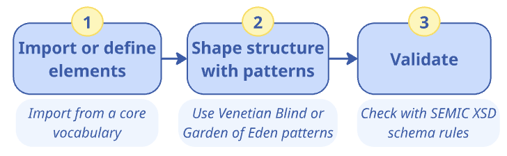
This section provides detailed instructions for addressing use case UC1.1. To create a new XSD schema, the following main steps need to be carried out:
-
Import or define elements
-
Shape structure with patterns
-
Validation
This is visualised in the following figure, together with key tasks and suggestions.
2.1.2.1. Phase 1: Import or define elements
When working with XML schemas, particularly in relation to semantic artefacts like ontologies or data shapes, managing the imports and namespaces are vital considerations that ensure clarity, reusability, and proper integration of various data models.
When a Core Vocabulary has defined an associated XSD schema, it is not only easy but also advisable to directly import this schema using the xsd:import statement. This enables seamless reuse and guarantees that any complex types or elements defined within the Core Vocabulary are integrated correctly and transparently within new schemas.
The imported elements are then employed in the definition of a specific document structure. For example, Core Vocabularies are based on DCTERMS that provides an XML schema, so Core Person could import the DCTERMS XML schema for the usage of a concept.
In cases where the Core Vocabulary does not provide an XSD schema, it is necessary to create the XML element definitions in the new XSD schema corresponding to the reused URIs. Crucially, these new elements must adhere to the namespace defined by the Core Vocabulary to maintain consistency; for the Core Vocabularies, they must be defined within the http://data.europa.eu/m8g/ namespace.
Furthermore, when integrating these elements into a new schema, it is essential to reflect the constraints from the Core Vocabulary’s data shape—specifically, which properties are optional and which are mandatory–within the XSD Schema element definitions.
|
Reusing elements and types from the Core Vocabulary improves interoperability and alignment with EU data standards, yet also imposes some limitations. Since reuse occurs at the syntactic level, element names and structures, including complex types, from the Core Vocabulary can be extended, but not easily restricted (for instance, limiting Organization to a single sub-organization would require creating a new complex type). These trade-offs between semantic interoperability and technical consistency are discussed in the Why Core Vocabularies section. |
2.1.2.2. Phase 2: Shape XML document structure
In designing XML schemas, the selection of a design pattern has implications for the reusability and extension of the schema. The Venetian Blind and Garden of Eden patterns stand out as preferable for their ability to allow complex types to be reused by different elements [dsg-ptr].
The Venetian Blind pattern is characterised by having a single global element that serves as the entry point for the XML document, from which all the elements can be reached. This pattern implies a certain directionality and starting point, analogous to choosing a primary class in an ontology that has direct relationships to other classes, and from which one can navigate to the rest of the classes.
Adopting Venetian Blind pattern reduces the variability in its application and deems the schema usable in specific scenarios by providing not only well-defined elements, but also a rigid and predictable structure.
On the other hand, the Garden of Eden pattern allows for multiple global elements, providing various entry points into the XML document. This pattern accommodates ontologies where no single class is inherently central, mirroring the flexibility of graph representations in ontologies that do not have a strict hierarchical starting point.
Adopting the Garden of Eden pattern provides a less constrained approach, enabling users to represent information starting from different elements that may hold significance in different contexts. This approach has been adopted by standardisation initiatives such as NIEM [niem] and UBL [ubl], which recommend such flexibility for broader applicability and ease of information representation.
However, the Garden of Eden pattern does not lead to a schema that can be used in final application scenarios, because it does not ensure a single stable document structure but leaves the possibility for variations. This schema pattern requires an additional composition specification. For example, if it is used in a SOAP API [soap-api], the developers can decide on using multiple starting points to facilitate exchange of granular messages specific per API endpoint. This way the XSD schema remains reusable for different API endpoints and even API implementations.
Overall, the choice between these patterns should be informed by the intended use of the schema, the level of abstraction of the ontology it represents, and the needs of the end-users, aiming to strike a balance between structure and flexibility.
We consider the Garden of Eden pattern suitable for designing XSD schemas at the level of core or domain semantic data specifications, and the Venetian Blind pattern suitable for XSD schemas at the level of specific data exchange or API.
|
Recommendation for choosing the appropriate pattern: The Venetian Blind Pattern suits an API where a central entity is the main entry point, offering a structured schema for defined use cases. The Garden of Eden Pattern is better for Core or Domain Data Specifications, where multiple entry points provide flexibility for general-purpose data models. |
Complex types should be defined, if deemed necessary, only after importing or defining the basic elements and application of patterns. Complex types are deemed complex when they have multiple properties, be they attributes or relationships.
Finally, complete the XSD schema by adding annotations and documentation, which improve understanding of the schema’s content both for external users and oneself at a later date, as well as communicating the purpose so that the schema will be deployed as intended.
|
Add annotations and documentation using the |
2.1.2.3. Phase 3: Validation
The schema should be validated with at least one sample XML document, to verify that it is syntactically correct, semantically as intended, and that it has adequate coverage. SEMIC XSD schemas adhere to best practices and the resulting XSD schemas should also adhere to best practices, the SEMIC Style Guide, validation rules to maintain consistency, clarity, and reusability across schemas. These rules include naming conventions, documentation standards, and structural rules.
Having created the XML representation from the Core Vocabulary, we thus created a binding between the technical and semantic layer for the interoperability of the data. Either may possibly evolve over time and changes initiated from either direction should be consulted with the other, and may require re-validation of the binding. Strategies to avoid problematic divergence are to be put in place.
2.1.3. Tutorial: Create an XSD schema using the Core Business Vocabulary
Creating an XSD schema using the Core Business Vocabulary (CBV) involves defining the structure, data types, and relationships for the elements of the CBV, ensuring interoperability between systems. This tutorial follows the guidelines outlined for Use Case UC1.1 "Create a New XSD Schema", showing how to design and create an XSD schema that integrates terms from the Core Business Vocabulary (CBV). This step-by-step guide focuses on the essential phases of the schema creation process, ensuring that the elements from CBV are correctly imported, the document structure is shaped properly, and all constraints are applied.
To recap the process, we first will import or define elements, shape the structure with patterns, define complex types, and finalise the schema.
2.1.3.1. Phase 1: Import or define elements
Managing Imports and Namespaces
In XML Schema development, managing imports and namespaces is crucial to ensure that elements from external vocabularies are reused and integrated consistently. This step ensures that the schema obtains and maintains semantics, will be reusable, and is correctly aligned with the Core Business Vocabulary (CBV).
For example, CBV comes with its own XSD schema, the following import statement imports all definitions related to CBV elements into your XSD schema (explained afterwards):
<?xml version="1.0" encoding="UTF-8"?>
<xs:schema
  xmlns:xs="http://www.w3.org/2001/XMLSchema"
  targetNamespace="http://data.europa.eu/m8g/xsd"
  xmlns="http://data.europa.eu/m8g/xsd"
  xmlns:dct="http://purl.org/dc/terms/"
  xmlns:sawsdl="http://www.w3.org/ns/sawsdl"
  elementFormDefault="qualified"
  attributeFormDefault="unqualified"
  version="2.2.0">

  <!-- Importing Core Business Vocabulary schema -->
  <xs:import
    namespace="http://data.europa.eu/m8g/"
    schemaLocation="https://raw.githubusercontent.com/SEMICeu/XML-schema/refs/heads/main/models/CoreVoc_Business/CoreVoc_Business.xsd"/>
</xs:schema>
The key components are:
-
<xs:import>: The element that imports the CBV schema to make its terms available in your schema. -
namespace="http://data.europa.eu/m8g/": Defines the namespace of the CBV. -
schemaLocation="https://raw.githubusercontent.com/SEMICeu/XML-schema/main/models/CoreVoc_Business/CoreVoc_Business.xsd": Points to the location of the CBV schema file on the Web.
Define elements
If the XSD schema of the CV does not suffice, in that you need additional elements beyond the XSD schema, then you have to define those yourself in the XSD schema you are developing. This might be an element from the CV associated with the XSD, or possibly elements from another CV or semantic artefact.
These new elements need to adhere to the Core Vocabulary’s namespace to maintain consistency.
For example, the LegalEntity element could be defined as follows if no XSD is provided for it:
<xs:element name="LegalEntity" type="LegalEntityType"/>Make sure you declare the correct namespace (e.g., http://example.com/) for all these custom elements.
2.1.3.2. Phase 2: Shape the XML document structure with patterns
At this phase, we focus on structuring the XML document using appropriate XML Schema Design Patterns [dsg-ptr]. The Venetian Blind and Garden of Eden patterns are two methods for organizing the schema.
Venetian Blind Pattern
In the Venetian Blind pattern, there is one primary global element, and all other elements are nested inside it. This approach is ideal when a central entity, such as LegalEntity, serves as the entry point, as seen in CBV’s XSD. This pattern fits well with API design, where you typically request information about a central concept (such as LegalEntity), and the response includes nested properties, including LegalName and RegisteredAddress, which are all organised under the main entity.
Here’s an example, where LegalEntity serves as the main entry point:
<xs:schema
  targetNamespace="http://data.europa.eu/m8g/xsd"
  xmlns="http://data.europa.eu/m8g/xsd"
  xmlns:xs="http://www.w3.org/2001/XMLSchema"
  xmlns:dct="http://purl.org/dc/terms/"
  xmlns:sawsdl="http://www.w3.org/ns/sawsdl">

  <xs:element name="LegalEntity" type="LegalEntityType"/>
  <xs:element name="LegalName" type="TextType"/>
  <xs:element name="RegisteredAddress" type="AddressType"/>

  <!-- Other elements -->

</xs:schema>
In this example:
-
LegalEntityis the global entry point. -
It uses
LegalEntityType, which contains various properties such asLegalNameandRegisteredAddress.
Garden of Eden Pattern
In the Garden of Eden pattern, there are multiple entry points in the XML document. This is more flexible and is suitable when no central class is inherently the main starting point. The elements that are declared directly under <xs:schema> qualify as such entry points. In CBV these include LegalEntity, Organization etc., whereas nested elements, such as RegisteredAddress or ContactPoint, are defined inside those complex types and cannot start a document on their own.
<xs:schema xmlns:xs="http://www.w3.org/2001/XMLSchema">
  <xs:element name="LegalEntity" type="LegalEntityType"/>
  <xs:element name="Organization" type="OrganizationType"/>
</xs:schema>
Define Complex Types
After importing or defining the basic elements and structuring your XML document with patterns, the next step in creating an XSD schema is to define complex types. Complex types are used to represent business entities that contain multiple properties or relationships. For CBV, these types often model entities like LegalEntity or Organization, which have both simple and complex elements. For example, the LegalEntityType and OrganizationType, as follows.
An implemented LegalEntity might contain multiple child elements, such as LegalName modelled as a simple string, RegisteredAddress (also a complex type), and other related elements. Here’s how LegalEntityType is defined in the XSD schema:
<xs:complexType name="LegalEntityType"
  sawsdl:modelReference="http://www.w3.org/ns/legal#LegalEntity">
  <xs:sequence>
    <xs:element
      ref="LegalName"
      minOccurs="0"
      maxOccurs="unbounded"
      sawsdl:modelReference="http://www.w3.org/ns/legal#legalName"/>
    <xs:element
      ref="RegisteredAddress"
      minOccurs="0"
      maxOccurs="unbounded"
      sawsdl:modelReference="http://data.europa.eu/m8g/registeredAddress"/>
    <!-- More elements as needed -->
  </xs:sequence>
</xs:complexType>|
The sawsdl:modelReference annotation is used to link the element to an external concept, providing semantic context by associating the element with a specific vocabulary or ontology. |
Similar to the LegalEntityType complex type, the BusinessAgentType defines a concept with multiple properties and relationships. However, for BusinessAgentType in the XSD schema, we define it as a complex type that contains hierarchical relationships, such as HeadOf and MemberOf.
<xs:complexType name="BusinessAgentType"
  sawsdl:modelReference="http://xmlns.com/foaf/0.1/Agent">
  <xs:sequence>
    <xs:element
      ref="HeadOf"
      minOccurs="0"
      maxOccurs="unbounded"
      sawsdl:modelReference="http://www.w3.org/ns/org#headOf">
    </xs:element>
    <xs:element
      ref="MemberOf"
      minOccurs="0"
      maxOccurs="unbounded"
      sawsdl:modelReference="http://www.w3.org/ns/org#memberOf">
    </xs:element>
  </xs:sequence>
</xs:complexType>
It’s important to observe that in this context, LegalEntityType is defined as an extension of FormalOrganizationType (which, in turn, extends OrganizationType), declared using an <xs:extension base="…"> element, as shown in the following snippet.
<!-- LegalEntityType -->
<xs:element name="LegalEntity" type="LegalEntityType"/>

<xs:complexType name="LegalEntityType"
  sawsdl:modelReference="http://www.w3.org/ns/legal#LegalEntity">
  <xs:complexContent>
    <xs:extension base="FormalOrganizationType"/>
  </xs:complexContent>
</xs:complexType>
Finalise the XSD schema
Adding annotations and documentation to each complex type and element helps to clarify their purpose and improve the readability of the schema. For instance:
<xs:complexType name="BusinessAgentType"
  sawsdl:modelReference="http://xmlns.com/foaf/0.1/Agent">
  <xs:annotation>
    <xs:documentation xml:lang="en">
      Entity that is able to carry out action.
    </xs:documentation>
  </xs:annotation>
</xs:complexType>
2.1.3.3. Phase 3: Validation and best practices
Finally, test your new schema by validating sample XML documents using XML validation tools (e.g., XMLValidation) to ensure that the schema is syntactically correct and works as expected. The Core Business Vocabulary (CBV) follows several best practices and validation rules to maintain consistency, clarity, and reusability across schemas. These rules include naming conventions, documentation standards, and structural rules.
Schematron Validation Rules
To ensure schema compliance, the Schematron rules provide automated checks. These rules cover key aspects such as type definitions, element declarations, metadata, and more. The detailed list of rules can be found here.
Running the Validation
You can execute the rules using the provided build.xml file, which leverages Apache Ant. The process validates the schema against the Schematron rules and generates HTML reports for easy inspection.
2.2. Create a new JSON-LD context definition from a Core Vocabulary (UC1.2)
2.2.1. Use case description
Public administrations often need to share information about their services with other organisations and the public. To do this effectively, the data must be easy to understand and work seamlessly across different systems. However, public services are becoming more complex, which means we need to capture more details, concepts, and relationships to handle various use cases. This was also the case in Norway, which came to a fruitful solution. Let us imagine how that might have happened in the following scenario as motivation for the use case, which is followed by a user story that summarises it.
Consider Nora, who works for the DiTFor, the Norwegian Digitalisation Task Force. Although Norway is not a member of the EU, it is closely associated with the EU through its membership in the European Economic Area (EEA) and the Schengen Area. As part of the EEA, Norway participates in the EU’s internal market and adopts many EU laws and regulations. Therefore there is a lot of cross-border collaboration with other member states and there is a number of publicly available resources for use and reuse to facilitate interoperable exchange, including a vocabulary that could be used for their generic framework for their digitalisation of administration of public services: the Core Public Service Vocabulary Application Profile (CPSV-AP). They extended it to fit better with their context and needs, such as having introduced RequiredEvidence, which provides a way to explicitly define the documentation or credentials needed to access a service, such as proof of address for a library card. The extension was published publicly as CPSV-AP-NO.
Happy with the outcome, Nora emailed the municipalities so that each city and town would be able to upgrade their system in the same way with CPSV-AP-NO, and so that DiTFor could still collect and integrate the data at the national level.
Meanwhile, the City of Oslo’s transportation services department had just learned of smart data models to manage the data about public road network maintenance, such as dataModel.Transportation, and their helpdesk for reporting road maintenance issues. That data, stored according to the smart data model, could then also be used for the public transport network management organisation to work towards the aim to make Oslo a Smart City. A popular language to specify smart data models is a JSON-LD context, because it helps structure the data so it can be easily shared and understood by different systems.
The City of Oslo received DiTFor’s notification about the CPSV-AP-NO: their data models needed to comply with the CPSV-AP-NO for the purposes of effective use and interoperability. Looking into the details, they realised that it should be possible to utilise CPSV-AP-NO for their smart data model in JSON-LD and, in fact, would save them time looking for other vocabularies and adapting those. The question became one of how to do it, and so they replied to Nora’s email inquiring whether she could also provide instructions for using the Application Profile.
User Story: As a software engineer at a public sector department, I want to create a new JSON-LD context based on the Core Public Services Vocabulary Application profile (CPSV-AP), so that I can create interoperable smart data models that comply with national and European interoperability standards and support linked data publication to facilitate cross-system data exchange.
This business case translates into the following use case specification, which is instantiated from the general UC1.2 description in the previous section.
Use Case UC 1.2: Create a new JSON-LD context |
Goal: Create a new JSON-LD context that links to the CPSV-AP. |
Primary Actors: Semantic Engineer and Software Engineer |
Description: : Design and implement a new JSON-LD context definition for the transportation services department of Oslo that adheres to, and takes as input, the nationally relevant vocabulary of the CPSV-AP (i.e., CPSV-AP-NO). Carry out the task in a systematic way following an agreed-upon guideline.
|
Having established the who, what, and why, the next step is how to accomplish this. The semantic engineer specifies the guidelines for JSON-LD context development from a vocabulary, which makes it easier for the software engineer to implement it. The guideline is described in the next section.
2.2.2. Guidelines to create a new JSON-LD context definition
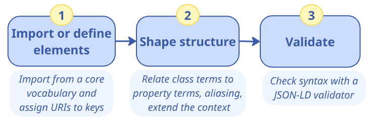
This section provides guidelines for addressing use case UC1.2.
JSON-LD is a W3C Recommendation for serialising Linked Data, combining the simplicity, power, and Web ubiquity of JSON with the concepts of Linked Data. Creating JSON-LD context definitions facilitates this synergy. This ensures that when data is shared or integrated across systems, it maintains its meaning and can be understood in the same way across different contexts. This guide describes how to create new JSON-LD contexts for existing Core Vocabularies.
The three key phases are:
-
Import or define elements
-
Shape structure
-
Review and validate
This is visualised in the following figure, together with key tasks and suggestions.
2.2.2.1. Phase 1: Import or define elements
When a Core Vocabulary has an associated JSON-LD context already defined, it is not only easy, but also advisable to directly import this context using the @import keyword. This enables seamless reuse and guarantees that any complex types or elements defined within the vocabulary are integrated correctly and transparently within new schemas.
In cases where the Core Vocabulary does not provide an JSON-LD context, it is necessary to create the corresponding field element definitions for the reused URIs, in three steps:
-
Gather all the terms from the selected Core Vocabulary that need to be included in the JSON-LD context.
-
Decide the desired structure of the JSON-LD file, by defining the corresponding keys, such as
Person.givenName. These new fields must adhere to the naming defined by the selected Core Vocabulary to maintain consistency. -
Assign URIs to keys. Each term in the JSON-LD context must be associated with a URI from an ontology that defines its meaning in a globally unambiguous way. Associate the URIs established in Core Vocabularies to JSON keys using the same CV terms.
The ones that are imported by the Core Vocabularies, shall be used as originally defined.
Example: importing an existing context.
{
  "@context": {
    "@import": "https://example.org/cpsv-ap.jsonld"
  }
}
2.2.2.2. Phase 2: Shape structure
Main shaping of the structure
Start with defining the structure of the context by relating class terms with property terms and then, if necessary, property terms with other classes.
Commence by creating a JSON structure that starts with a @context field. This field will contain mappings from one’s own vocabulary terms to other’s respective URIs. Continue by defining fields for classes and subfields for their properties.
If the JSON-LD context is developed with the aim of being used directly in an exchange specific to an application scenario, then aim to establish a complete tree structure that starts with a single root class. To do so, specify precise @type references linking to the specific class.
If the aim of the developed JSON-LD context is rather to ensure semantic correspondences, without any structural constraints, which is the case for core or domain semantic data specification, then definitions of structures specific to each entity type and its properties suffice, using only loose references to other objects.
Example: defining a class with properties.
{
  "@context": {
    "Service": "http://example.org/Service",
    "Service.name": "http://purl.org/dc/terms/title"
  }
}
Design note: Flat vs scoped context disambiguation
When defining properties in a JSON-LD context, one has to consider how attribute names are disambiguated across different classes. Two main approaches can be adopted:
-
Flat context disambiguation. In this approach, and demonstrated in the previous example, each property is declared globally and identified by a fully qualified key (for example,
Service.name). This guarantees that each attribute is uniquely associated with its URI, even when the same property name appears in different classes. The flat approach is straightforward to generate automatically and ensures full disambiguation, which is why it is adopted by the SEMIC toolchain. However, it can result in less readable JSON structures, because the prefixed property names may appear verbose or repetitive. -
Scoped context disambiguation. A context can be defined per class, allowing property names such as name or description to be reused within each class-specific scope. This produces cleaner and more human-readable JSON but can be more complex to design and maintain. Scoped contexts often require explicit
@typedeclarations or additional range indicators to ensure that the correct mappings are applied during JSON-LD expansion.
The choice between flat or scoped contexts should be motivated by the expected use of the data. When contexts are generated automatically or used for large-scale data exchange, the flat approach offers simplicity and reliability. When contexts are manually authored or designed for human-facing APIs, scoped contexts may be preferable for improved readability, provided that their additional complexity is manageable.
Improvements to the structure
To meet wishes from API consumers, one may use aliasing of keywords, where a JSON-LD context element is given a more easily recognisable string.
One can also extend the context by reusing terms from Core Vocabularies, which can be achieved using the @import keyword if included as a whole. Also, single elements can be added, such as additional properties and mapping those to other vocabulary elements of other vocabularies.
2.2.2.3. Phase 3: Review and validate
First, one should review the created context against any prior requirements that may have been described: is all prospected content indeed included in the context?
Second, the syntax should be verified with a JSON-LD validator, such as JSON-LD Playground to ensure that the context is free of errors and all URLs used are operational.
Example: an error in the URL.
{
  "@context": [
    { "@import": "https://invalid-url/cpsv-ap.jsonld" }
  ]
}
2.2.3. Tutorial: Create a JSON-LD context from the CPSV-AP Core Vocabulary
This tutorial addresses the use case UC1.2, and will show how to create a JSON-LD context for an Application Profile that extends CPSV-AP with new concepts that are defined by reusing concepts from the Core Business Vocabulary (CBV), following ideas from CPSV-AP-NO.
2.2.3.1. Phase 1: Import or define elements
Since CPSV-AP provides an existing JSON-LD context, we can import it in our own JSON-LD context using the @import statement. For example, in case of CPSV-AP version 3.2.0, the context can be directly reused like this:
{
  "@context": {
    "@import": "https://raw.githubusercontent.com/SEMICeu/CPSV-AP/master/releases/3.2.0/context/cpsv-ap.jsonld"
  }
}
If a context does not exist, define the elements explicitly. For example, CPSV-AP uses specific terms such as PublicService and ContactPoint. These terms must be mapped to URIs.
{
  "@context": {
    "PublicService": "http://purl.org/vocab/cpsv#PublicService",
    "ContactPoint": "http://data.europa.eu/m8g/ContactPoint"
  }
}
If a context needs to be extended, define the new elements explicitly. For example, if we need new terms (classes), such as Service and RequiredEvidence, which are not in CPSV-AP these terms must be mapped to URIs (the examples are inspired by CPSV-AP-NO):
{
  "@context": {
    "Service": "http://example.com/cpsvap#Service",
    "RequiredEvidence": "http://example.com/cpsvap#RequiredEvidence"
  }
}
Once you’ve imported or defined the relevant terms, you need to structure your JSON-LD context to reflect the relationships between the classes and their properties. This allows you to describe public services and their details in a standardised and machine-readable format.
Let’s look at an example where we define a Service and some of its key properties, such as contactPoint, description, name and hasRequiredEvidence:
{
  "@context": {
    "@import": "https://raw.githubusercontent.com/SEMICeu/CPSV-AP/master/releases/3.2.0/context/cpsv-ap.jsonld",
    "Service": "http://example.com/cpsvap#Service",
    "Service.hasRequiredEvidence": {
      "@id": "http://example.com/cpsvap#RequiredEvidence",
      "@container": "@set"
    },
    "Service.description": {
      "@id": "http://purl.org/dc/terms/description",
      "@type": "http://www.w3.org/1999/02/22-rdf-syntax-ns#langString",
      "@container": "@set"
    },
    "Service.name": {
      "@id": "http://purl.org/dc/terms/title",
      "@type": "http://www.w3.org/1999/02/22-rdf-syntax-ns#langString",
      "@container": "@set"
    },
    "Service.contactPoint": {
      "@id": "http://data.europa.eu/m8g/contactPoint",
      "@type": "@id",
      "@container": "@set"
    }
  }
}
Explanation of JSON-LD keywords used:
-
@context: Defines the mapping between terms (e.g., PublicService) and their corresponding IRIs. -
@container: Specifies how values are structured. For instance,-
@set: Explicitly defines a property as an array of values. It ensures that even if the data includes just one value, it will still be treated as an array by JSON-LD processors. This makes post-processing of JSON-LD documents easier as the data is always in array form, even if the array only contains a single value
-
-
@id: Provides the unique identifier (IRI) for a term or property. -
@type: Specifies the type of a value, which is commonly used for linking to classes or data types. -
@import: Imports another JSON-LD context, allowing reuse of its terms.
Example of a simple service instance
After defining the context and structure, you can now describe an actual Service instance by referencing the terms you defined earlier.
Example scenario
Let’s assume a public administration offers a service called "Health Insurance Registration". This service allows citizens to register for health insurance, which requires certain documents (evidence) to complete the process. Citizens might need to contact the administration for guidance, and the service details should be structured in a way that makes it easy to share and integrate across systems.
To illustrate this, we need to create a JSON-LD context representation of this service, highlighting
-
The required evidence for registration (e.g., proof of address);
-
The service’s name and description for clarity;
-
Contact information for users who may need assistance.
Try this in the JSON-LD Playground here and then check your solution with the example below.
{
  "@context": [
    "https://raw.githubusercontent.com/SEMICeu/CPSV-AP/master/releases/3.2.0/context/cpsv-ap.jsonld"
  ],
  "@id": "http://example.org/service/healthInsuranceRegistration",
  "@type": "PublicService",
  "PublicService.name": {
    "@value": "Health Insurance Registration",
    "@language": "en"
  },
  "PublicService.description": {
    "@value": "A service for registering for health insurance.",
    "@language": "en"
  }
}
Aliasing keywords for API compatibility (REST API example)
When working with REST APIs, it is often beneficial to alias certain JSON-LD keywords for simpler or more consistent representations in client applications. For example, you might alias JSON-LD’s @id to url and @type to type to make the data more intuitive for API consumers, especially when working with legacy systems or client-side frameworks that use specific naming conventions.
Example of aliasing keywords
{
  "@context": {
    "url": "@id",
    "type": "@type",
    "Service": "http://purl.org/vocab/cpsv#PublicService",
    "Service.name": "http://purl.org/dc/terms/title",
    "Service.description": "http://purl.org/dc/terms/description"
  },
  "url": "http://example.com/service/healthInsuranceRegistration",
  "type": "Service",
  "Service.name": "Health Insurance Registration",
  "Service.description": "A service for registering for health insurance."
}
In this example, url is an alias for @id and type is an alias for @type.
By aliasing these terms, the API responses are simplified and more familiar to the developers interacting with the service, especially if they are accustomed to a different JSON structure.
Extend the context by reusing terms from Core Vocabularies
To highlight the reuse of terms from existing CVs, we can import the Core Business Vocabulary (CBV) context alongside the CPSV-AP context to gain access to business-related terms. This step ensures that you can use the additional terms from CBV, such as LegalEntity, Organisation, and ContactPoint, to enrich your Service descriptions.
{
  "@context": [
    {
      "@import": "https://raw.githubusercontent.com/SEMICeu/CPSV-AP/master/releases/3.2.0/context/cpsv-ap.jsonld"
    },
    {
      "@import": "https://raw.githubusercontent.com/SEMICeu/Core-Business-Vocabulary/master/releases/2.2.0/context/core-business-ap.jsonld"
    }
  ]
}
Define additional properties from the Core Business Vocabulary
Add CBV terms to enhance the description of the Service entity by reusing existing concepts such as LegalEntity, which helps to specify who provided the service.
{
  "@context": {
    "Service.providedBy": {
      "@id": "http://example.com/legal#providedBy",
      "@type": "http://example.com/legal#LegalEntity"
    },
    "LegalEntity": "http://www.w3.org/ns/legal#LegalEntity"
  }
}
Map extended properties in a service instance
Use the extended properties to describe more aspects of Service instances. For example:
{
  "@context": [
    "https://raw.githubusercontent.com/SEMICeu/CPSV-AP/master/releases/3.2.0/context/cpsv-ap.jsonld",
    "https://raw.githubusercontent.com/SEMICeu/Core-Business-Vocabulary/master/releases/2.2.0/context/core-business-ap.jsonld",
    {
      "ex": "http://example.org/"
    }
  ],
  "@id": "http://example.org/service/healthInsuranceRegistration",
  "@type": "PublicService",
  "PublicService.name": {
    "@value": "Health Insurance Registration",
    "@language": "en"
  },
  "PublicService.description": {
    "@value": "A service for registering for health insurance.",
    "@language": "en"
  },
  "ex:providedBy": {
    "@id": "http://example.org/legalEntity/healthDepartment",
    "@type": "LegalEntity"
  }
}
Final review and validation
Use a JSON-LD validator (there are online tools available, such as the JSON-LD Playground) to validate JSON-LD context and make sure there are no errors. They also offer visualisation features, noting that it can only be visualised if the syntax is correct. There is no standard for how RDF graphs are to be rendered, and therefore different visualisation tools will result in different JSON-LD diagram-based visualisations. Below are two examples generated from the same JSON-LD snippet, rendered by, JSON-LD Playground and :isSemantic, respectively.
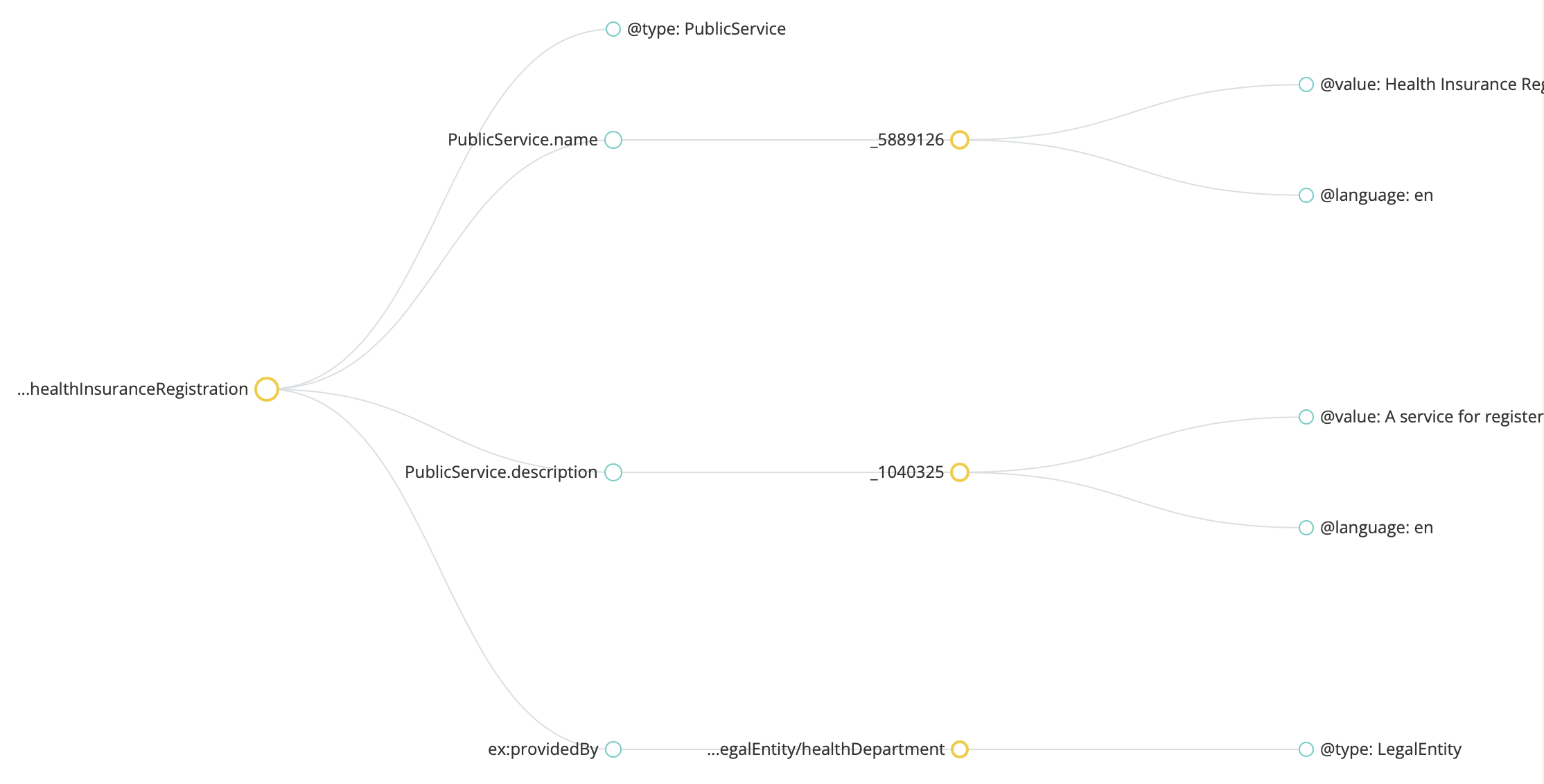
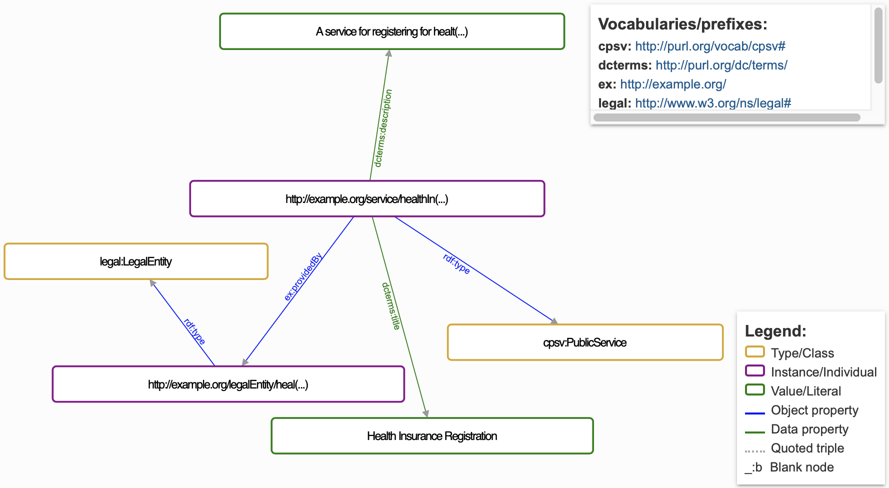
Error example
If the @import URLs for external contexts are incorrect or unavailable, the validation tool may display an error such as:
-
"Error loading remote context" or
-
"Context could not be retrieved."
{
 "@context": [
  { "@import": "https://invalid-url/cpsv-ap.jsonld" }
 ]
}
These errors typically occur when the referenced context URL is malformed or unreachable, as shown in the following figure:
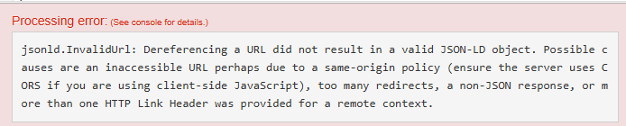
How to resolve the error
Ensure that the @import URLs point to valid and accessible JSON-LD contexts. Verify the links in a browser or test them in a cURL command to ensure they return the correct JSON-LD data (cURL is used in command lines or scripts to transfer data). Update the URLs to the correct ones.
3. Mapping an existing model to Core Vocabularies
In the fields of knowledge representation and data modelling, distinct modelling languages exist and their corresponding methods and tools to create them. While such heterogeneity can be useful, it also raises challenges for semantic interoperability.
The idea of unifying this broad spectrum of approaches under a single model and a single representation language is conceptually appealing but pragmatically unfeasible. Also, the diversity reflects the varied domains, perspectives, and requirements these approaches and modelling languages serve.
To navigate this complexity, a nuanced approach is required—one that seeks to establish connections across models without imposing uniformity. Here, the notions of ontology matching and model alignment methodologies more generation come into play, using the term ‘ontology’ loosely in this context (i.e., it may also refer to similar artefacts, such as OWL-formalised conceptual data models or structured controlled vocabularies). The mapping endeavour encompasses not only ontological artefacts, vocabularies, and application profiles, but also various technical artefacts, such as data shapes defined in SHACL, XSD schemas for XML and to JSON schemas for JSON data. Thus, mapping in this broader sense involves creating links between these semantic and technical artefacts and Core Vocabularies.
The past three decades have witnessed extensive efforts in ontology and attendant model matching, resulting in a plethora of tools, methods, and technologies. These strategies range from concept-based methods that focus on the semantic congruence and contextual relevance of the model elements, to formal methods for finding, aligning, and transforming content to cater for various mapping needs.
The subsequent sections describe the guidelines of model mapping and thereby provide an entry point for navigating and bridging the world of semantic and technical artefacts, empowering stakeholders in the process.
The use cases focus on mapping two types of models specifically: conceptual models (or application ontologies) and XSD schemas. They each have their business cases providing a rationale for why one would want to do this, which is described in the respective “Description” sentences. The respective “Guidelines” sections describe the general procedure on how to map the model that may be read by both intended audiences. The respective “Tutorial” sections are principally aimed at the technical experts and IT professionals.
3.1. Map an existing conceptual model to a Core Vocabulary (UC2.1)
3.1.1. Use case description
Imagine different organisations using different words of the same language. One system refers to an “Organisation,” while another calls it a “LegalEntity.” Both are describing the same concept—but their data structures, labels, and assumptions differ slightly. Without a shared understanding, exchanging data between these organisations becomes error-prone, inconsistent, or simply impossible.
Let’s consider a scenario as motivation for the use case and the corresponding structured user story.
Sofía, a knowledge engineer working in the Department of Agriculture and Natural Resources, faces the problem of terminological overloading and mismatches. Her Fruits division uses a conceptual model that was developed to represent companies, directors, and contact details of fruit orchards and industrial forest agribusinesses, while a different one is used by the Vegetables division that needs to be aligned at a later date. To solve this, Sofía leads a project that maps her Fruits division’s model to the Core Business Vocabulary (CBV), a semantic standard developed by SEMIC.
Meanwhile, external platforms—such as international business directories, government data portals, and the Schema.org vocabulary used by major web platforms—represent similar concepts differently. So do the Chamber of Commerce and the Department of the Economy, from which she wants to use data.
Sofía recognises the widespread use of Schema.org, and so she also wants to ensure that the CBV concepts she uses can be mapped to Schema.org’s content. She can do this by creating semantic bridges between the models used in her division of the Department, CBV, and global vocabularies.
User Story: As a knowledge engineer at the Department of Agriculture, I want to map my division’s existing conceptual model to the Core Business Vocabulary (CBV) and align CBV concepts with Schema.org, so that our data can be interoperable with both EU semantic standards and global web vocabularies, enabling accurate data exchange.
The business case translates into the following use case specification, which is instantiated from the general UC2.1 description:
Use Case UC 2.1: Map an existing conceptual model to a Core Vocabulary |
Goal: Create a mapping between the terms of the CBV and Schema.org. |
Primary Actors: Knowledge Engineer |
Description: Create formal mappings between relevant terms in the CBV and Schema.org, availing of standard Semantic Web technologies and alignment tools, and implement the mappings. |
3.1.2. Guidelines on how to map an existing conceptual model to a Core Vocabulary
This section provides general guidelines to address use case UC2.1, mapping an ontology to a Core Vocabulary.
In this section we adopt the definitions from the ontology matching handbook [om] for the following concepts:
-
Ontology matching process: given a pair of ontologies, a (possibly empty) input alignment that may help bootstrap the process, a set of parameters and additional resources, the process returns an alignment between these ontologies.
-
Correspondence: given a pair of ontologies, a set of alignment relations (typically equivalence and subsumption) and a confidence structure for those alignments, then a correspondence is a 5-tuple consisting of an identifier of the correspondence, the two entities (one from each ontology), how the two entities relate, and a measure of the confidence in that alignment.
-
Alignment: a set of correspondences between pairs of entities belonging to two ontologies.
-
Mapping: a set of correspondences between pairs of entities belonging to two ontologies, and this mapping is satisfiable and does not lead to unsatisfiable entities in either of the two ontologies that are being matched.
To create an ontology mapping, the following steps need to be observed, as shown in the following diagram and described afterwards.
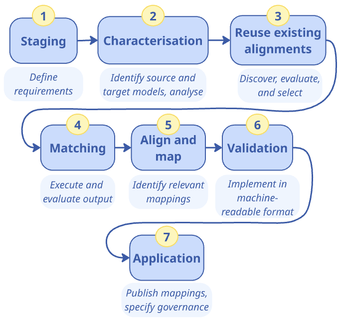
-
Staging: defining the requirements;
-
Characterisation: defining source and target data and performing data analysis;
-
Reuse: discover, and, if existing alignments are found, to evaluate and reuse existing alignments;
-
Matching: execute and evaluate matching;
-
Align and map: prepare, create the alignment, and render mappings;
-
Validate: check whether the candidate alignments found are meaningful;
-
Application: publish the mappings and establish governance of the mappings.
This section provides an overview of the guideline, which will be demonstrated in the tutorial section where we map the Core Business Vocabulary to Schema.org. The reader familiar with ontology matching could skim or skip it and proceed swiftly to the tutorial section.
3.1.2.1. Phase 1: Staging
This initial phase involves a comprehensive understanding of the project’s scope, identifying the specific goals of the mapping exercise, and the key requirements it must fulfil. Stakeholders collaborate to articulate the purpose of the alignment between the models, setting clear objectives that will guide the process. Defining these requirements upfront ensures that subsequent steps are aligned with the model matching process’ overarching goals, stakeholder expectations, and fitting the use cases.
Inputs: Stakeholder knowledge, project goals, available resources, domain expertise.
Outputs: Mapping project specification document comprising a well-defined scope and comprehensive list of requirements.
3.1.2.2. Phase 2: Characterisation
In this phase, a thorough analysis of both source and target ontologies is conducted to ascertain their structures, vocabularies, and the semantics they encapsulate. This involves an in-depth examination of the conceptual frameworks, representation languages, and the models. Understanding the models’ respective nuances is critical for identifying potential challenges and opportunities in the matching process to determine whether the process will be feasible and meaningful.
The following list of features is indicative, but not exhaustive, in this analysis: specifications’ documentation, representation language and representation formats, deprecation mechanism, inheritance policy (single inheritance only or multiple inheritance are also allowed), natural language(s) used, label specification, label conventions, definition specification, definition conventions, and version management and release cycles.
These features can have consequences for the mapping task. Let us illustrate three of them. For instance, the files being available in the same format, such as both in JSON-LD, simplifies declaring and implementing the mappings technically, whereas if they are in a different format, one will have to be converted into the other format, if it is possible to do so without loss of meaning.
The natural language of the ontology or vocabulary refers to the rendering of the entities’ names or labels, which may be one language, multiple languages equally, one language mainly and others with partial coverage. For instance, the source ontology may have French and English labels for most elements that are identified by an identifier like XYZ:0012345, but either lapsed in translating a few terms or the developers could not find a suitable equivalent in one of the two, such as Fleuve and Riviere in French for which only River exists in English, and the target ontology could have element names in English only rather than identifiers with human-readable labels. If the source and target are in a different natural language, the task is not simply one of mapping entities, but also translating names, labels, and annotations of entities.
An infrequently updated version can indicate either that it is a stable release or that it is not maintained, and the comparison thus depends on a broader setting that may be worthwhile to ascertain. Conversely, a frequently updated version is less stable, and it may even be the case that by the time a matching process is completed with one version, a new version has been released that might require an update to the mapping.
Depending on the feature, one will have to inspect either the computer-processable file or the dedicated documentation that describes it, or both.
Inputs: Source and target ontologies, requirements, and any business or domain constraints.
Outputs: Analysis reports comprising a comparative characterisation table, identified difficulties, risks and amenability assessments, selected source and target for mapping.
3.1.2.3. Phase 3: Reuse
In the ontology matching lifecycle, the reuse phase is important in that it can facilitate the integration of already existing mappings into the project’s workflow, thereby saving work and positioning one’s ontology better within the existing ecosystem. Following the initial characterisation, this phase entails the discovery and evaluation of available mappings against the project’s defined requirements. These requirements are instrumental in appraising whether an existing alignment can be directly adopted, requires modifications for reuse, or if a new alignment should be declared.
Ontology alignments are often expressed in Alignment Format (AF) [af] or Expressive and Declarative Ontology Alignment Language (EDOAL) [edoal, al-api].
The outcome of this activity can be either of:
-
direct reuse of mappings that are immediately applicable,
-
adaptive reuse where existing mappings provide a partial fit and serve as a basis for refinement of the mapping, and
-
the initiation of a new alignment when existing resources are not suitable.
This structured approach to reuse optimises resource utilisation, promotes efficiency, and tailors the mapping process to the project’s unique objectives.
Inputs: Repository of existing alignments for the source and target ontologies, evaluation criteria based on requirements.
Outputs: Assessment report on existing alignments, decisions on reuse, adaptation, or creation of a new alignment.
3.1.2.4. Phase 4: Execute the matching
This section summarises automatic and semi-automatic approaches to finding the alignment candidates. In case of small vocabularies and ontologies, a fully manual effort is likely more efficient.
Utilising both automated tools and manual expertise, this phase focuses on identifying potential correspondences between entities in the source and target models. The matching process may employ various methodologies, including semantic similarity measures, pattern recognition, or lexical analysis, to propose candidate alignments. These candidates are then evaluated for their accuracy, relevance, and completeness, ensuring they meet the requirements and are logically sound. This phase consists of three main activities: planning, execution, and evaluation.
In the planning activity, the approach to ontology matching is strategised, which encompasses selecting appropriate methods with their algorithms and tools, fine-tuning parameters, determining thresholds for similarity and identity functions, and setting evaluative criteria. These preparations are informed by a thorough understanding of the project’s requirements and the outcomes of previous reuse evaluations.
Numerous well-established ontology matching algorithms have been extensively reviewed in the literature (for a review and in-depth analysis, see [om-lr, om]). The main categories of ontology matching techniques are listed below in the order of their relevance to this handbook:
-
Terminological techniques draw on the textual content within ontologies, such as entity labels and comments, employing methods from natural language processing and information retrieval, including string distances and statistical text analysis.
-
Structural techniques analyse the relationships and constraints between ontology entities, using methods like graph matching to explore the topology of ontology structures.
-
Semantic techniques apply formal logic and inference to deduce the implications of proposed alignments, aiding in the expansion of alignments or detection of conflicts.
-
Extensional techniques compare entity sets, or instances, potentially involving analysis of shared resources across ontologies to establish similarity measures.
Next, the execution activity implements the chosen matchers. Automated or semi-automated tools are deployed to carry out the matching process, resulting in a list of candidate correspondences. This list typically includes suggested links between elements of the source and target ontologies, each with an associated confidence level computed by the algorithms [edoal]. A language for expressing such correspondences is commonly used to declare these potential alignments.
Finally, in the evaluation activity, the alignments found are rigorously assessed on their suitability. The evaluation measures the alignments against the project’s specific needs, scrutinising their accuracy, relevance, and alignment with the predefined requirements, so that only the most suitable alignments are carried forward for the creation of a mapping, thereby upholding the integrity and logical soundness of the matching process.
3.1.2.5. Phase 5: Validate alignments
Following the identification of alignments, this step involves the formal creation of the alignment and the rendering (generation) of specific mappings between the source and target models. This phase involves preparing, creating, and rendering activities that establish coherent actionable mappings between ontology entities. The resulting alignment is then documented, detailing the rationale, methods used, and any assumptions made during the mapping process.
The alignment process may include engaging communication with third parties to validate the alignment. Furthermore, the process has technical implications that should be evaluated upfront, such as the machine interpretation and execution of the mapping.
Preparation involves stakeholder involvement to collectively go systematically through the list of alignments (candidate mappings), considering not only the relevance of the alignments, but also the type of relationship between the elements, being typically either equivalence or subsumption.
The type of asset—an ontology, controlled list, or data shape—dictates the nature of the relationship that can be rendered from the alignment. The types of alignment are visually represented and illustrated in the figure below and summarised and structured in the table afterwards. They include alignment elements for OWL elements concerning semantic artefacts and for SKOS, which can be used for annotations and weakly semantic knowledge organisation systems.
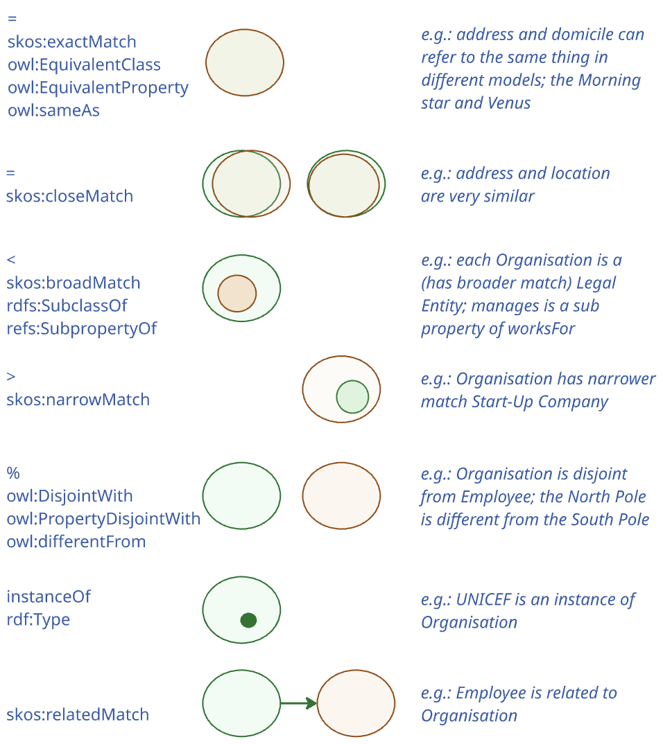
| Relation / Element type | Property | Concept | Class | Individual |
|---|---|---|---|---|
= |
owl:equivalentProperty; owl:sameAs |
skos:exactMatch; skos:closeMatch |
owl:equivalentClass; owl:sameAs |
owl:sameAs |
> |
skos:narrowMatch |
|||
< |
rdfs:subPropertyOf |
skos:broadMatch |
rdfs:subClassOf |
|
% |
owl:propertyDisjointWith |
owl:disjointWith |
owl:differentFrom |
|
instanceOf |
rdf:type |
skos:broadMatch; rdf:type |
rdf:type |
rdf:type |
hasInstance |
skos:narrowMatch |
The table is indicative of the variety of semantic connections that can be realised, including equivalence, subclass, disjointness, and type instantiation. This nuanced preparation is key to ensuring that the final alignment and mapping reflect the project’s semantic requirements and scope accurately.
The Creation step is the execution of the mapping, entailing the selection of the relation, and assertion of the mapping. This activity involves human intervention and the selection is conducted manually according to the project’s objectives and semantic appropriateness of the candidate mapping.
Rendering translates the mapping in a machine-readable format so that it can be interpreted and executed by software agents. Typically, this is a straight-forward export of the alignment statements from the editing tool or the materialisation of the mapping in a triple store, using a common format, such as Alignment Format [af], EDOAL [edoal], Simple Standard for Sharing Ontological Mapping (SSSOM) [sssom], and the Semantic Mapping Vocabulary (SEMAPV) [semapv] for the mapping justification values. Multiple renderings may be created from the same alignment, accommodating the need for various formalisms.
Tools: Tools such as VocBench3 [vocbench] can be used in this phase, or generic office tools, such as MS Excel, Google Sheets spreadsheets, or a LibreOffice spreadsheet.
Inputs: Evaluated correspondences (the alignments), stakeholders' amendment plans, requirements for the formalism of the mapping so that the mapping assertions integrate with the modelling language used.
Outputs: Created mapping, stored versions in an alignment repository (e.g., [sem-map]).
3.1.2.6. Phase 6: Application
The final phase focuses on operationalising the created mappings, ensuring it is accessible and usable by applications that require semantic interoperability between the mapped models. This involves carrying out the following tasks:
-
Publish the mappings in the standardised, machine-readable format obtained from Phase 5, and
-
Establish mechanisms for maintaining, updating, and governing the alignment, facilitating its long-term utility and relevance.
Regarding the second task, governance involves the creation of maintenance protocols to preserve the alignment’s relevance over time. This includes procedures for regular updates in response to changes in ontology structures or evolving requirements, as well as governance mechanisms to oversee these adaptations. As the mapping is applied, new insights may emerge, prompting discussions within the stakeholder community about potential refinements or the development of a new iteration of the mapping. Due to the dynamic nature of data sources, the application phase serves both as an endpoint, as well as a foundation for continuous improvement. Some processes may be automated to enhance efficiency, such as the monitoring of ontologies for changes that would necessitate mapping updates.
Inputs: Finalised mappings, application context, feedback mechanisms.
Outputs: Applied mappings in use, insights from application, triggers for potential updates, governance actions for lifecycle management.
3.1.3. Tutorial: Map Schema.org to the Core Business Vocabulary
This tutorial demonstrates how to map Schema.org to the Core Business Vocabulary (CBV), addressing Use Case UC2.1. By following map an existing model methodology, you’ll learn how to align these two vocabularies step-by-step—covering staging, characterisation, reuse, matching, alignment, and application—to ensure interoperability between the CBV and Schema.org.
3.1.3.1. Phase 1: Staging (Defining the requirements)
In this phase, the aim is to understand what needs to be mapped and why.
For this tutorial, we aim to map Schema.org to the Core Business Vocabulary (CBV), enabling data interoperability.
Steps
-
Determine the purpose of the mapping project: What are the key areas of business data that need to be interoperable between CBV and Schema.org? This is carried out in collaboration with stakeholders.
-
Define scope of the mapping for the model and selected CV: What parts of the Core Business Vocabulary need to be mapped to Schema.org? Are there specific concepts (e.g., contact point, organisation) that must be represented? Which version of each ontology or vocabulary will be mapped?
-
Set specific goals of what the mapping needs to achieve: Define the intended specific outcomes of the mapping. Besides ensuring semantic alignment between CBV and Schema.org entities, a key goal may be to clarify the relationship between legal:LegalEntity and schema:Organization (Issue #38), or to declare a particular equivalence between a CBV and a Schema.org entity to query across information systems to retrieve data.
Output
A short project specification that defines the purpose of the mapping, its scope, and expected outcomes. For this tutorial, the output is:
-
Purpose: Enable semantic interoperability between business-related data models using CBV and Schema.org.
-
Scope: Map the CBV (source) concepts to Schema.org (target):
-
legal:LegalEntity → schema:Organization
-
m8g:Address → schema:PostalAddress
-
-
Goal: Allow transformation of CBV-compliant data into Schema.org format for reuse.
-
Expected Outcome: A validated alignment file that specifies the relationships between the selected CBV and Schema.org terms in machine-readable RDF.
Procedure for CBV and Schema.org
The purpose, scope, and goals are determined by the stakeholders, including domain experts and knowledge engineers. First, the domain experts’ input is needed to demarcate the scope especially, indicating what the (sub-)topic of interest is, ideally augmented with key terms. For CBV and Schema.org, these may include terms such as: legal:LegalEntity versus schema:Organization. It may also need to take into account ‘externalities’, such as regulatory compliance that may dictate the use of one version of a schema over another for some business reason. For the current exercise, there are no regulatory compliance requirements in place. Therefore, the latest official releases of both vocabularies will be used (Schema.org version 29.1 and CBV version 2.2.0). Next, clear mapping goals should be established. For this exercise, the primary goal is to identify direct relationships between the two vocabularies. These relationships will then be expressed in a machine-readable format, enabling seamless data transformation between the CBV and Schema.org.
3.1.3.2. Phase 2: Characterisation (Defining source and target models)
The aim of this phase is to analyse the structure, vocabulary, and semantics of the Core Business Vocabulary that we shall take as Target ontology and Schema.org that will be set as Source ontology. The key steps and outputs are as follows.
Steps
-
Examine both ontologies for:
-
Entity structures, definitions, and formats.
-
Deprecation policies and inheritance mechanisms, natural language(s) used, label specification, label conventions, definition specification, definition conventions, version management and release cycles, etc.
-
Output
-
A comparison in the form of a table
-
Optionally: a brief report containing a list of obstacles that need to be overcome before model matching can take place
Procedure for CBV and Schema.org
First, list the features on which to compare the source and the target, which concerns principally the ‘meta’ information, that is information about the artefacts themselves, rather than their subject domain content. This includes typical features such as the artefacts’ serialisation format(s), terms’ naming conventions, and version management. These features can either hinder or support the mapping task.
Let’s consider three of them and consider how they apply to our case.:
1) Are the files available in the same format? This is indeed the case for CBV and Schema.org, and even leaves the choice for using their RDF or JSON-LD format.
2) The natural language of CBV and Schema.org, that is, the rendering of the entities’ names and labels, are both in one language, and so translating entities’ names is not needed
3) Regarding frequency of version updates, there is a notable difference. CBV is relatively stable with two main releases, whereas Schema.org has frequent releases and it is currently in its 29th main release cycle.
The selected features are presented in a table below, where for each feature the corresponding values for CBV and Schema.org are provided for comparison. For the CBV and Schema.org metadata comparison, we had to consult the documentation, the developer release pages, and directly inspect the available files.
| Feature | Core Business Vocabulary | Schema.org |
|---|---|---|
Specification |
HTML document |
HTML document |
Computer processable formats |
UML, RDF, JSON-LD, SHACL |
OWL, RDF (ttl, rdf/xml), CSV, JSON-LD, NQ, NT, SHACL, SHEXJ |
Inheritance |
Single inheritance |
Multiple inheritance |
Label |
rdfs:label, shacl:name (within SHACL shapes) |
rdfs:label |
Naming scheme |
CamelCase for classes (e.g., LegalEntity) and lowerCamelCase for properties |
CamelCase for classes (e.g., EducationalOrganization) and lowerCamelCase for properties |
Label formatting |
With spaces (e.g., Legal Entity) |
In CamelCase |
Language |
English |
English |
Deprecation |
No |
Yes |
Definitions |
rdfs:comment, shacl:description within SHACL shapes |
Written in rdfs:comment |
Latest version inspected |
Latest (v 2.0.0, 6-5-2024). 1 or 2 releases per year |
29.0 (24-3-2025). 1 or 2 releases per year |
Developer location |
3.1.3.3. Phase 3: Reuse of existing mappings
The aim of this phase is to avoid doing duplicate work by checking if any existing mappings between CBV and Schema.org are available for reuse, or if there are any alignments that can be adapted for this project.
Steps
-
Search for Existing Alignments: Looking for any pre-existing alignments that may have been created by others or as part of previous work by consulting the SEMIC GitHub repository for relevant mappings.
-
Evaluate Reusability: Determine whether these existing alignments meet your project’s requirements. If they do, they can be reused directly.
-
Adapt Existing Alignments: If the existing alignments are close, but need modification, adapt them to suit the specific project goals.
Output
-
A document listing:
-
Which type of alignment was chosen for which existing alignments.
-
The decisions: A new alignment needs to be created.
-
Procedure for CBV and Schema.org
There are three distinct pathways, namely: direct use, adaptive reuse, and creating a new alignment. Let’s look at each in turn. For the CBV and Schema.org, we first look for pre-existing alignments of related vocabularies. They may be declared in the files themselves, but we also can search the SEMIC GitHub repository for other files that may have relevant mappings already.
In the SEMIC repository, there are several vocabularies that have alignments to Schema.org already, which may be reusable. They are listed in the following table, along with the location and the latest version available at the the day of the exercise (recall the Source and Target Characterisation above).
| Mapping From | Mapping To | Location | Version |
|---|---|---|---|
CBV |
Schema.org |
https://github.com/SEMICeu/Semantic-Mappings/tree/main/Core%20Business |
CBV v2.2.0 – Schema.org v29.1 |
We then look at the intersection of CBV concepts and relationships and those in Schema.org. If there are shared or closely related terms, we check whether a mapping already exists between those specific elements. This takes us to the Evaluate reusability step: and if it is an agreeable mapping between the two entities, we can reuse that mapping. Alternatively, it may be the case of adaptive reuse, which involves refinements to better suit the mapping objectives.
-
Example: An existing alignment for LegalEntity to Organization was evaluated. However, it was missing relationships for properties like schema:legalName and schema:taxID. So, the original alignment was extended to include new mappings for these properties. There may also be new alignments when existing resources are not suitable, which is the case for this tutorial.
-
Example: Add alignment to answer the question: What is the relation between legal:LegalEntity and schema:Organization?
3.1.3.4. Phase 4: Matching (execute and filter matching candidates)
At this step, we will perform the actual mapping, which we shall bootstrap by producing candidate mappings between classes and between properties, typically automatically, semi-automatically, or manually, and then assess the results.
Steps
-
Select Matching Technique: Decide on a method for automatically or semi-automatically matching entities.
-
Perform Matching: Prepare the inputs and use the chosen tool to generate potential matches between CBV and Schema.org entities.
-
Candidate Evaluation: The knowledge engineer assesses the candidate correspondences for their consistency, accuracy, relevance, and alignment with the project’s requirements, which involves human evaluation.
Output
-
List of alignments.
Procedure for CBV and Schema.org
In this tutorial, we use LIMES [limes] to automate link discovery in the mapping process between the CBV and Schema.org. While other tools could also be used, LIMES was selected for its simplicity and efficiency in performing lexical similarity-based alignments.
Set Up Data Sources
Preparing the data sources depends on the files and the alignment tool chosen. To support this, the table of features compiled in Phase 2 is useful. It indicates whether alignment should be run on class names or labels, specifies the file format, and notes any algorithmic peculiarities, such as a similarity threshold. For our use case, we begin by configuring the SPARQL endpoints, which allow us to extract the relevant classes and properties for comparison. We focus on aligning entities by their rdfs:label whose value is the name or description of the entity, which is the most straightforward way to identify potential mappings.
Apply Matching Algorithm
LIMES uses a similarity metric to compare the rdfs:label values of entities from both files. This metric generates similarity scores based on the string matching of the labels and, optionally, their descriptions.
Analyse Results
Tools such as LIMES and Silk do not determine the semantic nature of the match (e.g., equivalence vs. subclass). They only suggest candidate pairs based on similarity metrics. It is up to the human expert to choose the appropriate relation, using knowledge of the domain and the ontology documentation. Once the matching process is complete, we inspect the results. In the case of the CBV and Schema.org alignment, no matches were found with LIMES, which means that no significant similarities were identified between entities based on the chosen similarity metric. Consequently, we need to either try with another alignment tool or manually review and align the entities. While we opt for the latter, let us first illustrate how the output would look if there had been potential matches. The LIMES output includes three key columns:
-
Source entity: a URI from the target ontology (e.g., Schema.org).
-
Target entity: a URI from the source ontology (e.g., CBV).
-
Similarity score: a numerical value (typically from 0 to 1) indicating the strength of the lexical similarity between the two entities.

Manual Alignment Process
Even though the automated tool did not produce any alignments, we can use our domain knowledge to suggest potential mappings based on the descriptions and attributes of the entities. For example, CBV’s LegalEntity (that is an org:Organization) maps to Schema.org’s Organization based on their similar roles in representing business-related concepts, and likewise for CBV’s Address (imported from Core Location Vocabulary) with Schema.org PostalAddress. These kinds of alignments are made by examining the entity definitions and considering the context of their use in each ontology.
3.1.3.5. Phase 5: Validate alignments
After the alignments (i.e., candidate mappings) have been generated—either by automated tools or through manual assessment—each proposed mapping must be validated to assess if the candidate links represent semantically meaningful relationships between classes or properties from the two ontologies.
Steps
-
Confirm candidate correspondences with domain experts.
-
Review proposed alignments
-
Decide on the appropriate semantic relation. Common types that we focus on here include:
-
Equivalence: When two entities are conceptually and functionally the same → rendered as owl:equivalentClass or owl:equivalentProperty
-
Subsumption: When one entity is more specific than the other (i.e., subclass or subproperty) → rendered as rdfs:subClassOf or rdfs:subPropertyOf
-
-
Formalise the alignment into a mapping following conventions from the Alignment format or EDOAL.
-
-
Render Mappings in a Machine-Readable Format. The mapping file can be rendered in RDF/XML, Turtle, or other formats like JSON-LD, depending on the tool or system in use. The choice of format should align with the needs of the stakeholders and the technical requirements of the project. While RDF/XML is a standard format for machine-readable ontology representations, it may not be ideal for human consumption due to its complexity. However, RDF/XML (or other syntaxes such as Turtle) is often used in formal contexts for consistency and integration with other semantic web tools. If ease of use for human review is desired, a Graphical User Interface (GUI) or tools that visualise RDF data can provide a more intuitive way to view and edit mappings.
Output
-
Final alignment in RDF for integration
Procedure for CBV and Schema.org
Review Proposed Alignments
Each candidate correspondence is checked for correctness and relevance. For CBV and Schema.org, we use a manual inspection by ontology engineers first, which includes cross-referencing documentation or definitions. CBV’s LegalEntity is “A self-employed person, company, or organisation that has legal rights and obligations” and Schema.org’s Organization is “An organization such as a school, NGO, corporation, club, etc.”. For Address, the descriptions are as follows: “A spatial object that in a human-readable way identifies a fixed location” with a usage note indicating it to be understood as a postal address, and “The mailing address”, respectively.
Decide the Appropriate Semantic Relation
For each validated candidate pair, determine the type of semantic relation.
For our running example, CBV’s LegalEntity is almost the same as Schema.org’s Organization, but the latter does not have the “legal rights” constraint, and therefore, the appropriate semantic relation is that of subsumption. For the respective addresses, while CBV’s imported Address’ definition is broader than PostalAddress, and therefore suggesting a subsumption alignment as well, taking into account CBV’s usage note, it can be an equivalence alignment.
Formalise the Alignment
Once the relation is chosen, each alignment is encoded as a machine-readable RDF triple, typically in RDF/XML or Turtle format, suitable for integration and reuse.
The result is a validated alignment file, where each mapping is represented based on the Alignment Format or an extension thereof, such as EDOAL, as an align:Cell with:
-
The aligned entities (
align:entity1andalign:entity2) -
The chosen relation (
align:relation), being either subsumption “<” or equivalence “=” -
An optional confidence measure
-
Its corresponding meaning in the ontology (
owl:annotatedProperty) -
Further information on a mapping justification, which reuses the Simple Standard for Sharing Ontological Mapping SSSOM that, in turn, reuses the Semantic Mapping Vocabulary SEMAPV for the mapping justification values.
Example output of adding an alignment between legal:LegalEntity and schema:Organization:
<http://mapping.semic.eu/business/sdo/cell/21> a align:Cell;
align:entity1 <http://www.w3.org/ns/legal#LegalEntity>;
align:entity2 <https://schema.org/Organization>;
align:relation "<";
align:measure "1"^^xsd:float;
owl:annotatedProperty rdfs:subClassOf;
sssom:mapping_justification semapv:MappingReview .
where it can be seen that the “<” relation corresponds to rdfs:subClassOf and the mapping justification is MappingReview, which is as approved as it can be in SEMAPV terminology.
Other alignment examples and a complete file including prefixes can be viewed here.
3.1.3.6. Phase 6: Application (operationalise the mappings)
After alignments have been validated, the final step is to apply them in practice. This involves both technical integration and the establishment of a governance framework to ensure the mappings remain up to date and useful over time.
Steps
-
Publish the Mappings: Share the mappings in a standard format via a repository.
-
Integrate and Test: Deploy the mappings in semantic web tools or data integration workflows.
-
Establish Governance: Define a process for updating the mappings in response to changes in the source or target ontologies.
Output
-
Published mappings and insights for potential refinements.
Procedure for CBV and Schema.org
The mapping file (in RDF/Turtle format) resulting from our mapping exercise is published on the SEMIC GitHub repository. This allows for integration of the mapping output into validation tools used by Member States and other implementers to check CBV-compliant data against Schema.org requirements.
For testing, one could attempt to load the files in an editor that can read in the file of the chosen format, being Turtle for CBV, the Turtle version of Schema.org, and the alignment file, or run it through a syntax validator to verify that all is in order for deployment.
The governance structure for the ‘model mapped to CV’ is, in principle, on the side of the model. Practically, for this case with CBV and its mapping to Schema.org, both have an interest in governing it. From the CBV side, SEMIC is responsible for regularly monitoring updates in CBV vocabulary and Schema.org (e.g., new classes, renamed terms, deprecated elements) and applying updates where needed, ensuring that logged issues are addressed, and verifying that all links and namespaces remain functional. SEMIC is also expected to consider updates to CBV driven by evolving requirements (e.g., to make CBV multilingual) and plan any necessary changes accordingly, including assessing their potential impact on the mappings with Schema.org.
Real Example Using SPARQL Anything
To demonstrate the practical value of the mapping between CBV and Schema.org, we use SPARQL Anything to query instance data alongside the alignment file.
*Scenario: * We assume
-
A data file (
core-business-ap.ttl) contains an instance of legal:LegalEntity -
An alignment file (
Alignment-CoreBusiness-2.2.0-schemaorg.ttl) defines a mapping from legal:LegalEntity to schema:Organization.
SPARQL Query
PREFIX xyz:   <http://sparql.xyz/facade-x/data/>
PREFIX legal: <http://www.w3.org/ns/legal#>
PREFIX align: <http://knowledgeweb.semanticweb.org/heterogeneity/alignment#>
PREFIX rdf:   <http://www.w3.org/1999/02/22-rdf-syntax-ns#>

CONSTRUCT {
  ?s a ?entity2 .
}
WHERE {
  SERVICE x-sparql-anything:app/core-business-ap.ttl {
    ?s a ?entity1 .
  }
  SERVICE x-sparql-anything:app/Alignment-CoreBusiness-2.2.0-schemaorg.ttl {
    ?align a align:Cell ;
           align:entity1 ?entity1 ;
           align:entity2 ?entity2 .
    FILTER (?entity1 = legal:LegalEntity)
  }
}
What This Query Does
It checks for instances of legal:LegalEntity in the data file, and if the alignment file contains a mapping for it, it infers the equivalent or related Schema.org class (schema:Organization).
Output
<http://example.org/entities/Company123> a <https://schema.org/Organization> .3.2. Map an existing XSD Schema to a Core Vocabulary (UC2.2)
3.2.1. Use case description
Let’s introduce the motivation for the use case for Use Case 2.2 with a scenario and structured user story.
Ella works as a data integration specialist at the National Registry of Certified Legal Practitioners. For over a decade, her team has maintained a robust system for managing, among others, all law firms’ data in XML format, supported by an XSD schema. This schema defines the structure of all XML documents generated and processed by the registry, capturing details such as legal entities, addresses, and contact points. It’s stable, reliable, and embedded into the internal tool and data exchange interface the organisation uses. But governments across Europe are requested to align their digital data infrastructures with Semantic Web standards with the goal to make public sector data interoperable, discoverable, and reusable across borders. Ella’s National Registry has received a directive to publish its business data in RDF, using the SEMIC Core Business Vocabulary (CBV), which is already used in EU-level platforms.
To meet this requirement, Ella must map the Registry’s existing XSD schema to the CBV and transform their XML data into RDF.
User Story: As a data integration specialist at a public sector organisation, I want to map our existing XML Schema Definition (XSD) to the Core Business Vocabulary (CBV), so that I can transform our XML data into semantically enriched RDF that complies with European interoperability standards, supports linked data publication, and enables cross-system data exchange.
This business case translates into the following use case specification, which is instantiated from the general UC2.2 description:
Use Case UC 2.2: Map an existing XSD schema to a Core Vocabulary |
Goal: Map the National Registry of Certified Legal Practitioners’ XSD schema and XML data into SEMIC’s Core Business Vocabulary. |
Primary Actors: Semantic Engineer (Data Integration Specialist) |
Description: : Take as input the XSD schema of the National Registry, select corresponding data that adheres to that XSD schema, and create mapping rules from there to equivalent entities in the Core Business vocabulary. Ensure that these rules are machine-executable, and transform the content into a knowledge graph that is semantically faithful to the semantics represented in the original XML files.
|
3.2.2. Guidelines for mapping an existing XSD schema to a Core Vocabulary
This section provides detailed instructions for addressing use case UC2.2.
To create an XSD mapping, one needs to decide on the purpose and level of specificity of the XSD Schema mapping. It can range from producing a lightweight alignment at the level of vocabulary down to a full-fledged executable set of rules for data transformation. In most cases, the reason why this mapping is done, is to also transform the corresponding XML files adhering to the XSD schema into RDF. Therefore, we include this step in the guideline.
In this section we describe the procedures to follow, which vary by selected material and ultimate goal in the broader context. The diagram below depicts the general process to create an XSD Schema mapping and corresponding XML mappings, which is described afterwards.
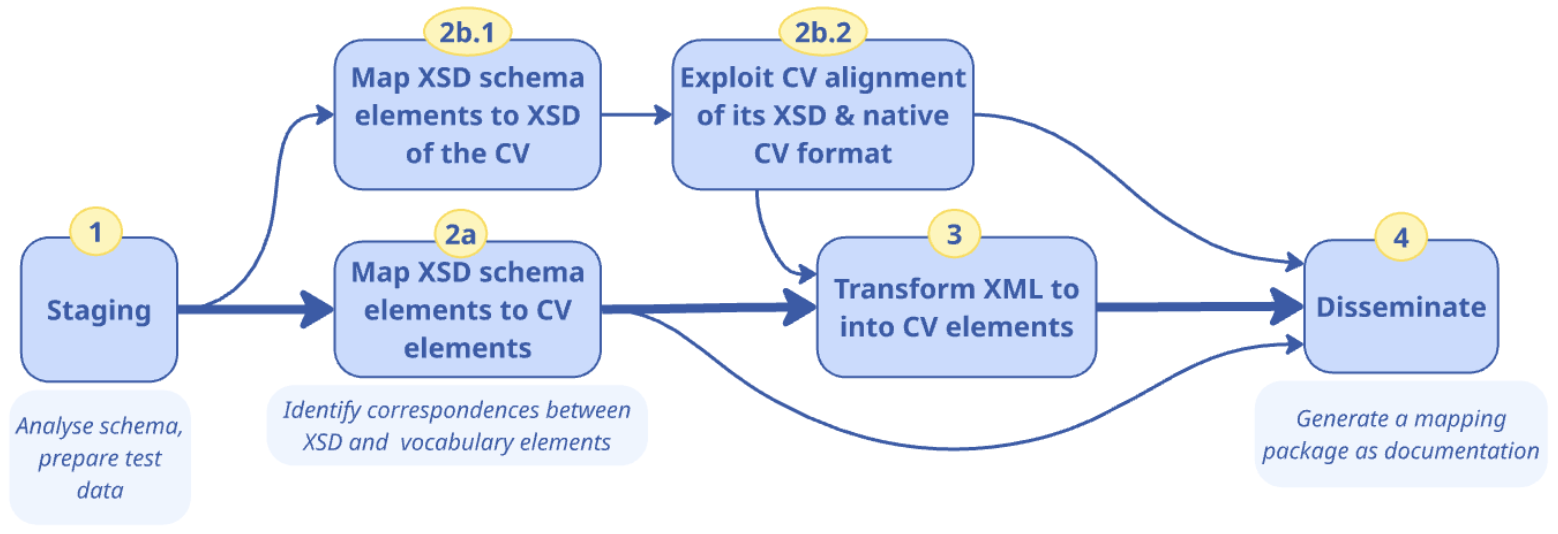
The main procedure consists of four phases:
-
Staging: to understand the XSD schema and prepare test data, to ensure any preparations are completed before the mapping process;
-
Map the XSD schema to the Core Vocabulary, for which there are two options:
-
Map the schema to the CV in its native format, which is the main scenario;
-
Map the schema to the XSD version of the CV, if such an XSD file is available;
-
-
Transform XML data to the Core Vocabulary through mappings, if applicable;
-
Disseminate the documentation according to the procedure followed including, mainly, the used and generated files, mapping declarations or rules, and validation reports, to be applied in the foreseen use cases of the transformation pipelines.
3.2.2.1. Phase 1: Understand the XSD schema and prepare test data
The first task is to examine the XSD schema to understand what elements it contains and how the hierarchical structuring of content may affect the meaning of the elements. This is important both for mapping and for selecting appropriate test data.
It may be that the XSD is outdated or partial with respect to the XML files that contain the data. Therefore, if during this staging process, it appears that Phase 3 will have to be included, then it is important to also construct a representative test dataset. This dataset should consist of a carefully selected set of XML files that cover the important scenarios and use cases encountered in the production data. It should be sufficiently comprehensive to facilitate rapid transformation cycles, enabling effective testing iterations in the validation. Also, it must align with the source schema for which it is used as test data.
3.2.2.2. Phase 2: Map the XSD schema
Conceptual Mapping in semantic data integration–determining what elements from the source should correspond to those in the target–can be established at two distinct levels: the vocabulary level and the application profile level. These levels differ primarily in their complexity and specificity regarding the data context they address. A Vocabulary mapping is established as the principal task: the XSD schema’s elements need to align to CV elements, focussing on terminological alignments.
For the XSD file, they are the elements within the tags <xs:element ref=”elementLabel”> where the “elementLabel” first has to be contextually interpreted if no definition is given in the XSD file, and then mapped to a concept from the chosen CV. For instance, a <xs:element ref=”address”> nested within the concept <xs:element ref=”Person”> has a different meaning from “address” nested within the concept <xs:element ref=”Website”>. This thus also requires careful management of the mappings, where the whole XPath is documented, rather than only the name of the element, because the whole path is needed for disambiguation.
Option 2-i. Map XSD to a CV’s main format
Mapping may be with the intent to transform, or simply align for interoperability. More tools have been proposed for the former, and more so explicitly to an OWL flavour (RDFS/OWL full or an OWL 2 in one of its serialisations).
A quick overview of translations for the XML Schema constructs and OWL constructs [xsd-owl] is included in the following table.
| XML Schema | OWL | Shared informal semantics element |
|---|---|---|
element|attribute |
rdf:Property, owl:DatatypeProperty, owl:ObjectProperty |
Named relationship between nodes or between nodes and values. |
element@substitutionGroup |
rdfs:subPropertyOf |
Relationship can appear in place of a more general one |
element@type |
rdfs:range |
The Class in the range position in the property |
complexType|group|attributeGroup |
owl:Class |
Relationships and contextual restrictions package |
complexType//element |
owl:Restriction |
Filler of a relationship in that axiom/context |
extension@base | restriction@base |
rdfs:subClassOf |
Indicates that the package concretises or specializes the base package. |
@maxOccurs @minOccurs |
owl:maxCardinality, owl:minCardinality |
Restrict the number of occurrences of a property |
sequence, choice |
owl:intersectionOf, owl:unionOf |
Combination of relations in a context |
An example of each XSD element/type to a class or property would, as a minimum, be recorded in a table format for documentation. For instance:
| XSD Element | Class/Property URI | Type |
|---|---|---|
xs:Legalobject |
ex1:LegalEntity |
Class |
xs:responsibleFor |
ex1:hasresponsibilityFor |
Property |
xs:RegisteredAddress |
ex1:OfficialAddress |
Property |
This approach results in a basic 1:1 direct alignment, which lacks contextual depth and specificity. Another approach would be to embed semantic annotations into XSD schemas using standards such as Semantic Annotations for WSDL and XML Schema (SAWSDL) [sawsdl] using the sawsdl:modelReference attribute to capture this mapping. Such an approach is appropriate in the context of WSDL services.
Option 2-ii. Map a XSD to the XSD of a CV
In a small number of cases, a CV also has an XSD schema derived from the CV’s main representation format. Then one could create an XSD-to-XSD mapping, i.e., from one’s own source XSD to the CV’s XSD target. Subsequently, it should be possible to use the CV’s existing alignment to obtain a source-XSD to target-CV alignment, by transitivity of the alignments, under the assumption that the alignment between the XSD of the CV and the CV is a 1:1 mapping. While this option is possible for the CBV already, it is currently not a main route for alignment to a CV and therefore not elaborated on further here.
After completing either Phase 2-i or 2-ii, one may proceed to Phase 3, if applicable, else jump to Phase 4.
3.2.2.3. Phase 3: Transform XML into CV elements
Drilling down into Phase 3 of the overall procedure, we identify three steps, as shown in the figure below.
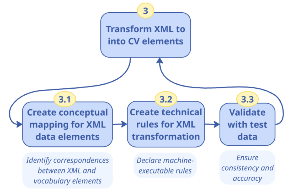
Transforming the XML data to the Core Vocabulary by means of mappings consists of:
-
Create a Conceptual Mapping, which involves defining the correspondence between the elements from the XSD schema, the terms in the vocabulary, and the elements in the corresponding XML files;
-
Create a Technical Mapping, which involves converting the conceptual mappings into machine-executable transformation rules, focussing on the actual transformation of XML to RDF;
-
Validate the mapping rules to test the mappings and data transformations on correctness;
The conceptual mapping helps business and domain experts to validate the correspondences. The technical mapping ensures an algorithm can transform the data automatically into a format that is compatible with the CV. The validation contributes to consistency and accuracy of the mappings and thereby the data transformation.
Phase 3.1 Conceptual Mapping development
Besides the XSD to CV mappings, the XML elements can also be mapped in a Vocabulary mapping. For the XML files, an XML element or attribute is then directly mapped to an ontology class or property. For example, an XML element <PostalAddress> could be mapped to the locn:Address class in a CV, or an element <surname> could be mapped to a property foaf:familyName in the FOAF ontology. Such mappings can be established and written in a spreadsheet or mapping-specific software.
Alternatively, one can create an Application Profile mapping, which utilises XPath to guide access to data in XML tree structures, enabling extraction and contextualization of data before mapping it to an ontology fragment that is usually expressed as a SPARQL Property Path (or simply: a Property Path). This Property Path facilitates the description of instantiation patterns specific to the Application Profile.
The tables below show two examples of mapping the organisation’s address, city and postal code: where the data is extracted from in the source, and how it can be mapped to targeted ontology, such as locn:postName, and locn:postCode in the vocabulary. To ensure that this address is linked to an organisation instance, and not, say, a person, the mapping is anchored in an instance represented by the variable ?this of an owl:Organisation. Optionally, a class path can also be provided to explicitly state the class sequence, which otherwise can be deduced from the Application Profile definition.
| Source XPath | */efac:Company/cac:PostalAddress/cbc:PostalZone |
|---|---|
Target Property Path |
?this cv:registeredAddress /locn:postCode ?value . |
Target Class Path |
org:Organization / locn:Address / rdf:PlainLiteral |
| Source XPath | */efac:Company/cac:PostalAddress/cbc:CityName |
|---|---|
Target Property Path |
?this cv:registeredAddress / locn:postName ?value . |
Target Class Path |
org:Organization / locn:Address / rdf:PlainLiteral |
Inputs: XSD schemas, Ontologies, SHACL Data Shapes, Source and Target Documentation, Sample XML data. Both vocabulary and profile mappings are typically crafted and validated by domain experts, data-savvy business stakeholders, and in collaboration with semantic engineers and CV experts.
Outputs: Conceptual Mapping documented in, e.g., a spreadsheet.
Phase 3.2: Technical Mapping development
The technical mapping serves as the bridge between conceptual design and practical, machine-executable implementation. This step takes as input the conceptual mapping and establishes correspondences between XPath expressions and ontology fragments.
Several technology options are available [ml-lr] to represent these mappings technically, such as XSLT [xslt], RML [rml] (extending R2RML), and [SPARQLAnything]. RML allows for the representation of mappings from heterogeneous data formats, such as XML, JSON, relational databases, and CSV into RDF. The mapping rules can be expressed in Turtle RML or the YARRRML [yarrrml] dialect, a user-friendly text-based format based on YAML, making the mappings accessible to both machines and humans. RML is well-supported by robust implementations such as RMLMapper [rml-map] and RMLStreamer [rml-stream], which provide robust platforms for executing these mappings. RMLMapper is adept at handling batch processing of data and RMLStreamer suits streaming data scenarios, where data needs to be processed in real-time.
Provided one has mastered RML along with XML technologies such as XSD, XPath, and XQuery to implement the mappings effectively [rml-gen], the development of the technical mapping rules is straightforward thanks to the conceptual mapping output from Phase 3.1. RML mapping statements are created for each class of the target ontology coupled with the property-object mapping statements specific to that class.
An additional step involves deciding on a URI creation policy and designing a uniform scheme for use in the generated data, ensuring consistency and coherence in the data output.
A viable alternative to RML is XSLT technology, which offers a powerful, but low-level method for defining technical mappings. While this approach allows for high expressiveness and complex transformations, it also increases the potential for errors due to its intricate syntax and operational complexity. This technology excels in scenarios requiring detailed manipulation and parameterisation of XML documents, surpassing the capabilities of RML in terms of flexibility and depth of transformation rules that can be implemented. However, the detailed control it affords means that developers must have a high level of expertise in semantic technologies and exercise caution and precision to avoid common pitfalls associated with its use.
A pertinent example of XSLT’s application is the tool for transforming ISO-19139 metadata to the DCAT-AP geospatial profile GeoDCAT-AP [geo-dcat-ap] in the INSPIRE framework and the EU ISA Programme. This XSLT script is configurable to accommodate transformation with various operational parameters such as the selection between core or extended GeoDCAT-AP profiles and specific spatial reference systems for geometry encoding, showcasing its utility in precise and tailored data manipulation tasks.
Inputs: Conceptual Mapping spreadsheet.
Outputs: Technical Mapping source code.
Phase 3.3: Validation of the RDF output
Given the output of Phase 3.2 and the test data preparation from Phase 1, first transform the sample XML data into RDF, which will be used for validation testing.
Two primary methods of validation should be employed to test the integrity and accuracy of the data transformation: SPARQL-based validation and SHACL-based validation, each serving distinct but complementary functions.
The SPARQL-based validation method utilises SPARQL ASK queries that are derived from the SPARQL Property Path expressions and complementary Class paths from Phase 3.1. The ASK queries test specific conditions or patterns in the RDF graph corresponding to each conceptual mapping rule. By executing these queries, one aims to confirm that certain data elements and relationships have been correctly instantiated according to the mapping rules. The ASK queries return a Boolean value indicating whether the RDF graph meets the conditions specified in the query, thus providing a straightforward mechanism for validation. This confirms that the conceptual mapping is implemented correctly in a technical mapping rule.
For example, for the mapping rules above, the following assertions can be derived:
ASK {
  ?this a org:Organization .
  ?this cv:registeredAddress / locn:postName ?value .
}
ASK {
?this a org:Organization .
?this cv:registeredAddress / locn:postCode ?value .
}The SHACL-based validation method provides a comprehensive approach for validating RDF data, where data shapes are defined according to the constraints and structures expected in the RDF output, as specified by the mapped Application Profile. These shapes act as templates that the RDF graph must conform to, covering aspects such as data types, relationships, and cardinality. A SHACL validation engine processes the RDF data against these shapes, identifying any violations that indicate non-conformity with the expected data model.
SHACL is a suitable choice to ensure adherence to data standards and interoperability requirements. This form of validation is independent of the way in which data mappings are constructed, focussing instead on whether the generated data conforms to established semantic models. It provides a high-level assurance that data structures and content meet the specifications.
SPARQL-based validation is tightly linked to the mapping process itself, offering a granular, rule-by-rule validation that ensures each data transformation aligns with the expert-validated mappings. It is particularly effective in confirming the accuracy of complex mappings and ensuring that the implemented data transformations precisely reflect the intended semantic interpretations, thus providing a comprehensive check on the fidelity of the mapping process.
Inputs: Sample data transformed into RDF, Conceptual Mapping, Technical Mapping, SHACL data shapes.
Outputs: Validation reports.
3.2.2.4. Phase 4: Dissemination
Once the XSD-to-XSD (to CV), XSD-to-CV, and, optionally, the XML to CV have been completed and validated, they can be packaged for dissemination and deployment. In particular if Phase 3 is needed, disseminating a mapping package facilitates their controlled use for data transformation, ensures the ability to trace the evolution of mapping rules, and standardises the exchange of such rules. This structured approach allows for efficient and reliable data transformation processes across different systems.
A comprehensive mapping package typically includes:
-
XSD-to-CV mappings as output of Phase 2, together with at least the source XSD and target CV.
-
XML-to-CV mappings (optional):
-
Conceptual Mapping Files: Serves as the core documentation, outlining the rationale and structure behind the mappings to ensure transparency and ease of understanding for both domain experts and engineers.
-
Technical Mapping Files: This contains all the mapping code files ([xslt], [rml], [SPARQLAnything], depending on the chosen mapping technology) for data transformation.
-
Additional Mapping Resources (if applicable): Such as controlled lists, value mappings, or correspondence tables, which are crucial for the correct interpretation and application of the RML code.
-
Test Data: Carefully selected and representative XML files that cover various scenarios and cases. These test data are crucial for ensuring that the mappings perform as expected across a range of real-world data.
-
Factory Acceptance Testing (FAT) Reports: They document the testing outcomes to guarantee that the mappings meet the expected standards before deployment. They are based on the SPARQL and SHACL validations conducted.
-
Tests Used for FAT Reports: The package also incorporates the actual SPARQL assertions and SHACL shapes used in generating the FAT reports, providing a complete view of the validation process.
-
-
Descriptive Metadata: Contains essential data about the mapping package, such as identification, title, description, and versions of the mapping, ontology, and source schemas.
Such a package is designed to be self-contained, ensuring that it can be immediately integrated and operational within various deployment scenarios, supporting not only the application, but also the governance of the mappings, ensuring they are maintained and utilised correctly in diverse IT environments. This systematic packaging addresses critical needs for usability, maintainability, and standardisation, which are essential for widespread adoption and operational success in data transformation initiatives.
Inputs: Conceptual Mapping spreadsheet, Ontologies or Vocabularies, SHACL Data Shapes, Sample XML data, Sample data transformed into RDF, Conceptual Mapping, Technical Mapping, SHACL data shapes, Validation reports.
Outputs: Comprehensive Mapping Package.
3.2.3. Tutorial: Map the Core Business Vocabulary from XSD to RDF
This tutorial addresses Use Case UC2.2, focussing on enabling semantic interoperability by mapping an existing XSD schema—specifically, the Core Business Vocabulary (CBV) XSD schema—to its corresponding RDF representation. This tutorial guides you through the key steps, involving:
-
Staging, to understand the XSD schema;
-
Map the schema to the CV in its native format;
-
Map XML data into the CV’s native format:
-
Creating a conceptual mapping between the XSD schema and XML files, and the vocabulary in RDF;
-
Creating the technical mapping, defining the transformation rules;
-
Validating the RDF output;
-
-
Disseminating the outcome.
3.2.3.1. Phase 1: Staging
First, you will familiarise yourself with the selected XSD schema and then prepare the test data.
Understanding the XML schema
The CBV XSD file defines several key entities for the domain, including:
-
AccountingDocument: Financial and non-financial information resulting from an activity of an organisation.
-
BusinessAgent: An entity capable of performing actions, potentially associated with a person or an organisation.
-
FormalOrganization and LegalEntity: Legal and formal entities with rights and obligations.
-
ContactPoint: Contact details for an entity, such as email, phone, etc.
-
RegisteredAddress: The address at which the Legal Entity is legally registered.
Here’s how the snippet of the XSD schema looks like for the AccountingDocument:
<!-- AccountingDocumentType -->

<xs:element name="AccountingDocument" type="AccountingDocumentType"/>

<xs:complexType name="AccountingDocumentType"
  sawsdl:modelReference="data.europa.eu/m8g/AccountingDocument">
  <xs:annotation>
    <xs:documentation xml:lang="en">
      Financial and non-financial information as a result of an activity of an organisation.
    </xs:documentation>
  </xs:annotation>
</xs:complexType>
Preparing the Test Data
Since we will also map data and proceed through Steps 3.1-3.3 further below, it is essential to prepare representative test data in this Phase 1. This data should align with the structure defined in the XSD schema and cover various use cases and scenarios that might occur in production data. For this tutorial, we will use the SampleData_Business.xml file available on the SEMIC GitHub repository.
We ensure that the XML data contains relevant elements, such as <LegalEntity>, <LegalName>, <ContactPoint>, and <RegisteredAddress>, which you will later map to the CBV terms. Among other content, it has the following data for <LegalName>:
<LegalName xml:lang="fr">Comité belge pour l'UNICEF</LegalName>
<LegalName xml:lang="nl">Belgisch Comite voor UNICEF</LegalName>
3.2.3.2. Phase 2: Map XSD Schema elements to the XSD of the CV
Mapping XSD elements to CV Terms
In this step, we map each XSD element/type to Class or Property. These mappings often follow patterns like:
| XSD Element | RDF Class/Property URI | Type |
|---|---|---|
xs:LegalEntity |
legal:LegalEntity |
Class |
xs:LegalName |
legal:legalName |
Property |
xs:RegisteredAddress |
m8g:registeredAddress |
Property |
Use the sawsdl:modelReference attribute to capture this mapping.
Example Mapping Rules
Here’s how to describe mapping rules from XSD to TTL in XSD. For example:
<xs:element name="LegalName" type="TextType"
  sawsdl:modelReference="http://www.w3.org/ns/legal#legalName"/>
This maps the XML element <LegalName> to the property legal:legalName.
Mapping Table (Partial)
| XSD Element | RDF Mapping (TTL) |
|---|---|
|
a legal:LegalEntity |
|
legal:legalName "Example ORG." |
|
m8g:registeredAddress http://example.org/addr/123 |
3.2.3.3. Phase 3: Map XML data to the Core Vocabulary
Create a Conceptual Mapping
We will create a conceptual mapping between the XSD elements and RDF terms from the CBV. This will guide the transformation of the XML data to RDF. There are two levels of conceptual mapping:
-
Vocabulary Level Mapping: This is a basic alignment, where each XSD and XML element is directly mapped to an ontology class or property. For XSD, this task should already have been completed in Phase 2. Taken together, one then obtains an orchestration where, for instance,
<xs:element name="LegalEntity" type="LegalEntityType"/>from the XSD schema and the use of<LegalEntity>in the XML file are mapped to legal:LegalEntity. -
Application Profile Level Mapping: At this level, you use XPath expressions to extract specific data from the XML structure, ensuring a more precise mapping to the Core Vocabulary.
-
Example: Mapping the address fields from the XML to a specific property, such as locn:postCode or locn:postName. In both cases, the target is declared in two components: the target property path and the target class path, to ensure it is mapped in the right context. For instance, a locn:postName of a legal entity may well have different components compared to a locn:postName of the address of a physical building.
-
Conceptually, we thus map between the same things across the files, as illustrated in the following figure, which links the XSD element ContactPoint (highlighted with a green oval) to the cv:ContactPoint that, in turn, makes the contact point of the data (that adheres to the XSD schema specification) an instance of that contact point:
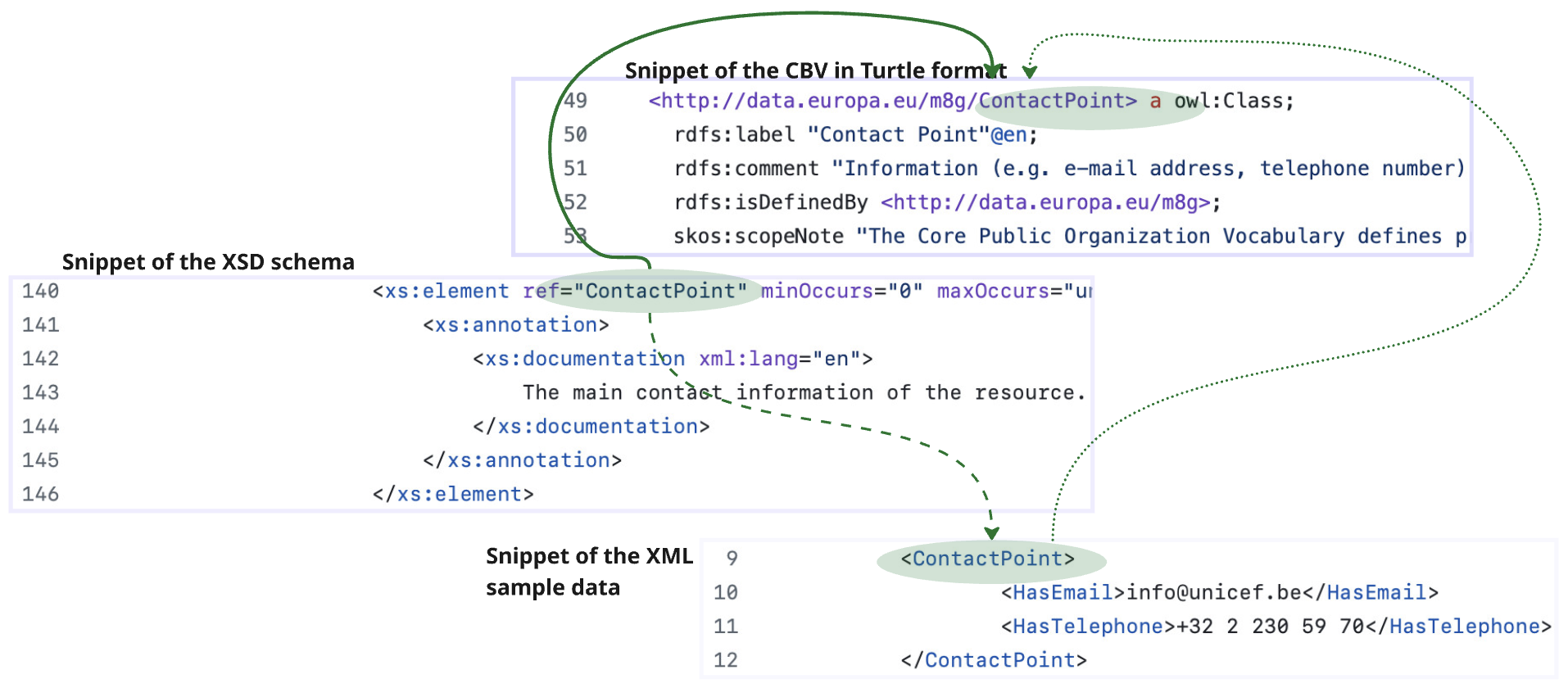
More precisely, you have to write down the source XPath, i.e., */ContactPoint in the figure, and how it is represented in the target specification, defining a target property path and a target class path. Examples of the Conceptual Mapping for five selected elements of the XSD schema are presented below, where the full URIs have been abbreviated:
| Source XPath | Target Property Path | Target Class Path |
|---|---|---|
*/AccountingDocument |
?this a cv:AccountingDocument . |
cv:AccountingDocument |
*/LegalEntity |
?this a legal:LegalEntity . |
legal:LegalEntity |
*/LegalEntity/LegalName |
?this legal:legalName ?value |
legal:LegalEntity |
*/ContactPoint |
?this a cv:ContactPoint . |
cv:ContactPoint |
Create the Technical Mapping
The RDF Mapping Language (RML) is suitable for the task of implementing the XML-to-RDF conceptual mappings as technical mappings. We will use RML to create machine-executable mapping rules as follows. First, the rml:logicalSource is declared, with the root of the tree in the XML file, which is */LegalEntity in our use case that assumes there to be an rml:source called SampleData_Business.xml with instance data. Next, a rr:subjectMap is added to state how each <LegalEntity> node becomes the RDF subject—here we build an IRI from generate-id(.) and type it as legal:LegalEntity. Finally, one or more rr:predicateObjectMap blocks capture the properties we need; in the simplest case we map the child element <LegalName> to the vocabulary property legal:legalName. The complete example RML mapping code looks as follows, in Turtle syntax:
@prefix rr:  <http://www.w3.org/ns/r2rml#> .
@prefix rml: <http://semweb.mmlab.be/ns/rml#> .
@prefix ql:  <http://semweb.mmlab.be/ns/ql#> .
@prefix ex:  <http://example.cv/mapping#> .
@prefix :    <http://example.cv/resource#> .
@prefix xsd: <http://www.w3.org/2001/XMLSchema#> .
@prefix legal: <http://www.w3.org/ns/legal#> .
@prefix rdfs: <http://www.w3.org/2000/01/rdf-schema#> .

ex:Organization
  a rr:TriplesMap ;
  rdfs:label "Organisation" ;
  rml:logicalSource [
    rml:source "SampleData_Business.xml" ;
    rml:iterator "*/LegalEntity" ;
    rml:referenceFormulation ql:XPath
  ] ;
  rr:subjectMap [
    rdfs:label "LegalEntity" ;
    rr:template "http://example.cv/resource#Organisation_{generate-id(.)}" ;
    rr:class legal:LegalEntity ;
  ] ;
  rr:predicateObjectMap [
    rdfs:label "LegalName" ;
    rr:predicate legal:legalName ;
    rr:objectMap [
      rml:reference "LegalName"
    ]
  ] .
This needs to be carried out for all elements from the XML files that were selected for mapping in Phase 1.
Validate the RDF Output
Now that we have created the mappings, we can apply them to sample data using RMLMapper or a similar tool selected from the SEMIC Tooling Assistant. For this tutorial, we will use RMLMapper, which will read the RML mapping file and the input XML data, and then generate the corresponding RDF output.
The snippet below is a single triple set produced when the mapping is run over the sample file SampleData_Business.xml (see Phase 1).
It shows that one of the XML <LegalEntity> records—the Belgian committee for UNICEF—has been converted into an RDF resource of type legal:LegalEntity with its legal:legalName correctly populated.
@prefix legal: <http://www.w3.org/ns/legal#> .
@prefix cv:    <http://data.europa.eu/m8g/> .
@prefix ex:    <http://example.cv/resource#> .

ex:Organization_1
    a legal:LegalEntity ;
    legal:legalName "Comité belge pour l'UNICEF"@fr ;
    legal:legalName "Belgisch Comite voor UNICEF"@nl .
We will validate the output in two ways: to check that the content transformed from XML into RDF exists in the graph and to check that it exists as intended also regarding any constraints on the shape of the graph.
First, we validate the generated RDF using SPARQL queries to ensure that the transformation adheres to the defined conceptual mapping. Since we want to validate rather than retrieve information, we use SPARQL ASK queries, which will return either a ‘yes’ or a ‘no’. For our running example, the SPARQL query for validating the LegalEntity is:
ASK {
  ?e a <http://www.w3.org/ns/legal#LegalEntity> ;
     <http://www.w3.org/ns/legal#legalName> ?name .
}
SHACL validation can be applied to ensure that the RDF data conforms to the required shapes and structures regarding any constraints that must hold.
To create a SHACL shape for the given RDF output, where the LegalEntity (legal:LegalEntity) has a legalName property, we need to define a SHACL shape that validates the type of the LegalEntity, the presence of the legalName property, and its datatype.
An example SHACL shape for validating LegalEntity is:
@prefix sh:    <http://www.w3.org/ns/shacl#> .
@prefix cv:    <http://data.europa.eu/m8g/> .
@prefix ex:    <http://example.cv/resource#> .
@prefix xsd:   <http://www.w3.org/2001/XMLSchema#> .
@prefix legal: <http://www.w3.org/ns/legal#> .

# Define a shape for LegalEntity
ex:LegalEntityShape
    a sh:NodeShape ;
    sh:targetClass legal:LegalEntity ;        # Applies to all instances of LegalEntity
    sh:property [
        sh:path legal:legalName ;             # Checks for the legalName property
        sh:datatype xsd:string ;              # Must be a string literal
        sh:minCount 1 ;                       # At least one legalName is required
    ] .
In this code snippet, observe:
-
Target Class: The shape is applied to all resources of type legal:LegalEntity. This means it validates any LegalEntity instance in the selected RDF data.
-
Property Constraints:
-
legal:legalName: The property legalName is required to be of type
xsd:string, and the minimum count is set to 1 (sh:minCount 1), meaning that the legalName property must appear at least once. Note: The SHACL shapes of the CBV can be found here.
-
3.2.3.4. Phase 4: Dissemination
Once the mappings are validated, the next step is to disseminate the project with the mappings as a package of documentation together with the artefacts. The package includes:
-
The source and target: the XSD schema and the CV;
-
Conceptual Mapping Files: This documents the mapping rules between XSD elements and RDF terms, being the table included above in Phase 2.
-
Technical Mapping Files: These include the RML or code for data transformation, which were developed in Phase 3.
-
Test Data: The representative set of XML files for testing the mappings that were created in Phase 1.
-
Validation Reports: The SPARQL and SHACL validation results obtained from Phase 4.
4. Concluding remarks
This Handbook demonstrated how Core Vocabularies can be used both to create new models and to map to existing ones, and that this can be achieved using various types of models, regardless of the syntaxes. This is exemplified by the guidelines for use, which were illustrated in four tutorials with concrete examples for a selection of popular syntaxes, including XML, JSON-LD, and RDF. Through implementation in concrete use cases, the Core Vocabularies function as a shared central reference, fostering interoperability as well as reducing design time for data stores and software applications.
The key task ahead is to promote broader adoption of Core Vocabularies initiating a process of continuous improvement - where early gains in interoperability inform SEMIC’s enhancements, leading to progressively greater alignment and efficiency.
This Core Vocabularies Handbook did not cover the following topics:
-
a complete methodology for syntax binding, as every step needed to turn a vocabulary into a validated, ready-to-use technical artefact (e.g., XSD, JSON-LD context, SHACL shapes);
-
data model library software infrastructure or tools to develop models and keep linked models in sync;
-
procedures for claiming conformance to a Core Vocabulary.
Claiming conformance to Core Vocabularies is an integral part of validating (a) how well a new or a mapped data model or semantic data specification aligns with the principles and practices established in the SEMIC Style Guide [sem-sg] and (b) to what degree the Core Vocabularies are reused (fully or partially) [sem-sg-reuse]. The conformance assessment is voluntary, and shall be published as a self-conformance statement. This statement must assert which requirements are met by the data model or semantic specification.
As a general guide for such a statement, we recommend it should note the level of adherence, ranging from basic implementation to more complex semantic representations. At the basic level, conformance might simply involve ensuring that data usage is consistent with the terms (and structure, but no formal semantics) defined by the Core Vocabularies. Moving to a more advanced level of conformance, data may be easily transformed into formats like RDF or JSON-LD, which are conducive to richer semantic processing and integration. This level of conformance signifies a deeper integration of the Core Vocabularies, facilitating a more robust semantic interoperability across systems. Ultimately, the highest level of conformance is achieved when the data is represented in RDF and fully leverages the semantic capabilities of the Core Vocabularies. This includes using a range of semantic technologies, adhering to the SEMIC Style Guide, fully reusing the Core Vocabularies, and respecting the associated data shapes.
The Core Vocabularies intend to remain ‘syntax neutral’; that is, they define concepts, properties, and constraints only at the semantic level and avoid prescribing any concrete/complete exchange format such as XML, JSON-LD, or RDF serialisation. Consequently, no tooling development to create the models is foreseen, or: modellers are free to use the tools they prefer to work with, also because such choices are dependent on the domain and the task at hand. With broader uptake, goalposts may shift, and a searchable data model library, such as those used for ontologies (e.g., [ols] [bp]), may become useful to further facilitate the uptake of Core Vocabularies by making them more easily findable.
Appendix: Additional Use Cases
The additional business and use cases are depicted in the diagram below and briefly described afterwards.
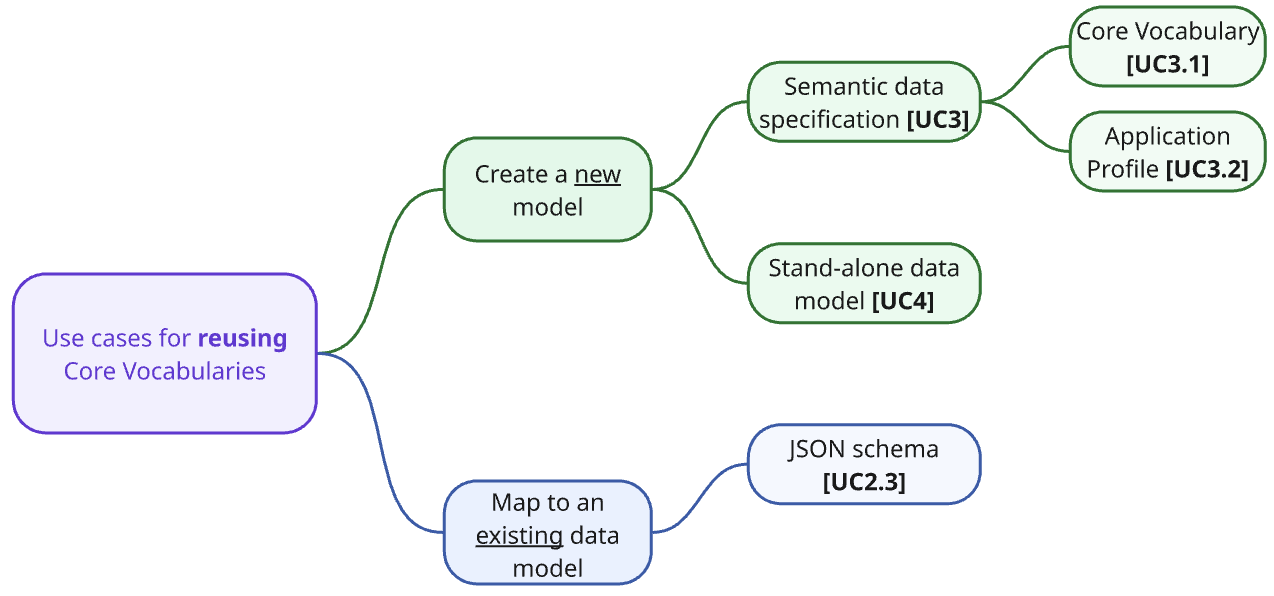
UC2.3: Map an existing JSON schema to a Core Vocabulary
A concrete user story can be formulated as follows:
User Story: As a semantic engineer at the Department of Justice, I want to map my JSON schema to the SEMIC Core Criterion and Core Evidence Vocabulary (CCCEV) so that we can transform our legal registry data into RDF that aligns with European interoperability standards, enabling cross-border reuse, and semantic integration.
To generalise from that to include other possible scenarios, we obtain the following use case description.
Use Case UC2.3: Map an existing JSON schema to a Core Vocabulary |
Goal: Define data transformation rules from a JSON schema to terms from Core Vocabularies. Create a mapping of JSON data that was created according to an existing JSON schema to an RDF representation that conforms to a Core Vocabulary for formal data transformation. Primary Actors: Semantic Engineer Actors: Domain Expert, Business Analyst, Software Engineer Description: The goal is to create a formal mapping using Semantic Web technology (e.g., RML or other languages), to allow automated translation of JSON data conforming to a certain JSON schema, to RDF data expressed in terms defined in one or more SEMIC Core Vocabularies. Such activity can be done by semantic engineers, based on input from domain experts and/or business analysts, who can assist with the creation of a conceptual mapping. The conceptual mapping is usually used as the basis for the formal mapping. The conceptual mapping can be a simple correspondence table associating the JSON data model elements defined in a JSON schema, to terms defined in one or more SEMIC Core Vocabularies. In some cases the creation of the conceptual mapping can be done by the semantic engineers themselves, or even by the software engineers building information exchange systems. |
UC3: Create a new Semantic data specification
The general case for creating a new semantic data specification is shown in the table below.
Use Case UC3: Create a new Semantic data specification |
Goal: Create a new semantic data specification that reuses terms from Core Vocabularies. Primary Actor: Semantic Engineer Description: The goal is to design and create a semantic data specification that represents the concepts in a particular domain, while reusing terms from existing CVs as much as possible for concepts that are already covered by CVs. Creating semantic data specifications using this approach will support better interoperability. Example: The eProcurement Ontology [epo] is a domain-specific semantic data specification built by reusing terms from multiple Core Vocabularies. Note: Recommendation on how to address this use case can be found in the Clarification on “reuse” section of the SEMIC Style Guide, and therefore will not be addressed in this handbook. |
Use Case UC3.1: Create a new Core Vocabulary
A concrete user story can be formulated as follows:
User Story: As a semantic engineer at the Department of Justice, I want to develop a new Core Vocabulary for the Transnational Incidents that will reuse terms from existing Core Vocabularies (e.g., CBV, CPOV), so that the new vocabulary is aligned with established standards and is interoperable with other domains.
Use Case UC3.1: Create a new Core Vocabulary |
Goal: Create a new Core Vocabulary that reuses terms from other Core Vocabularies. Primary Actor: Semantic Engineer Description: The goal is to design and create a new Core Vocabulary that represents the concepts of a generic domain of high potential reusability, while reusing terms from existing CVs as much as possible for concepts that are already covered by those CVs. Example: The Core Business Vocabulary (CBV) [cbv] is built reusing terms from the Core Location Vocabulary (CLV) [clv] and Core Public Organization Vocabulary (CPOV) [cpov]. Note: Recommendation on how to address this use case can be found in the Clarification on “reuse” section of the SEMIC Style Guide, and therefore will not be addressed in this handbook. |
Use Case UC3.2: Create a new Application Profile
A concrete user story can be formulated as follows.
User Story: As a semantic engineer at the Department of Sanitation’s outreach team, I want to create a new application profile from the Core Public Event Vocabulary, so that not only the data about the events we organise align with EU terminology, but that other Departments’ outreach teams can use the same CPEV-AP as well, thereby saving them design time, and we could then link up the event listings and present it in one portal.
Use Case UC3.2: Create a new Application Profile |
Goal: Create a new Application Profile that reuses terms from other Core Vocabularies and specifies how they should be used. Primary Actor: Semantic Engineer Description: The goal is to design and create a new Application Profile that represents all the concepts and restrictions on those concepts that are relevant in a particular application domain, while reusing terms from existing CVs as much as possible. Example: The Core Public Service Vocabulary Application Profile (CPSV-AP) [cpsv-ap] is built reusing terms from the Core Location Vocabulary (CLV) [clv] and Core Public Organisation Vocabulary (CPOV) [cpov]. Note: Recommendation on how to address this use case can be found in the Clarification on “reuse” section of the SEMIC Style Guide, and therefore will not be addressed in this handbook. |
UC4: Create a new data model
The main use case is as follows, which is refined into two specific ones afterwards.
Use Case UC4: Create a new data model |
Goal: Create a new standalone data model artefact that reuses terms from Core Vocabularies. Primary Actor: Semantic Engineer Description: The goal is to design and create a new data model artefact that is not part of a more comprehensive semantic data specification, describing the concepts that are relevant in a particular domain or application context, while reusing terms from existing CVs as much as possible. Such an artefact can be of different nature both according to their interoperability layer (ranging from vocabulary and ontology, to data shape and data schema) and also according to their abstraction level (ranging from upper layer, through domain layer to application layer). Note: Since this is a more generic use case it will be broken down into more concrete use cases that focus on specific data models. See also some related use cases (UC1, UC1.1 and UC1.2) discussed in the main use cases section. |
Use Case UC4.1: Create a new ontology
A concrete user story can be formulated as follows.
User Story: As a semantic engineer at the National Library of Parliament, I want to create a new ontology about sittings and subcommittees of parliaments, reusing terms from the Core Public Event Vocabulary, and ensuring logical consistency with expressive constraints, so that I can reliably integrate parliament data across the different databases, classify meetings by type of meeting, annotate the parliamentary proceedings texts so that I can search by concept rather than string, and enhance the citizen chatbot about parliamentary proceedings.
Use Case UC4.1: Create a new ontology |
Goal: Create a new standalone ontology that reuses terms from Core Vocabularies. Primary Actor: Semantic Engineer Description: The goal is to design and create a new ontology that is not part of a more comprehensive semantic data specification, describing the concepts that are relevant in a particular domain or application context, while reusing terms from existing CVs as much as possible. Example: The eProcurement Ontology (ePO) [epo] is built reusing terms from multiple CVs, including the Core Location Vocabulary (CLV) [clv], Core Public Organisation Vocabulary (CPOV) [cpov] and Core Criterion and Core Evidence Vocabulary (CCCEV) [cccev]. Note: Recommendation on how to address this use case can be found in the SEMIC Style Guide (more specifically in the Clarification on “reuse” section and the various Guidelines and conventions subsections), and therefore will not be addressed in this handbook. |
Use Case UC4.2: Create a new data shape
A concrete user story can be formulated as follows.
User Story: As a semantic engineer at SMECor GmbH, I want to adapt the Core Evidence Vocabulary Application Profile (CCCEV-AP) to add more precise constraints, such as that each piece of evidence must be created by exactly one Agent, and create corresponding data shapes so that I can check the constraints in our company’s knowledge graph and ensure that it adheres to our business rules regarding filing and tracing evidence.
Use Case UC4.2: Create a new data shape |
Goal: Create a new standalone data shape that specifies restrictions on the use of terms from Core Vocabularies. Primary Actor: Semantic Engineer Description: The goal is to design and create a new data shape that is not part of a more comprehensive semantic data specification, describing the expected use of concepts that are relevant in a particular domain or application context, including the use of terms from existing CVs. Note: Recommendation on how to address this use case can be found in the SEMIC Style Guide (more specifically in the Clarification on “reuse” and Data shape conventions sections), and therefore will not be addressed in this handbook. |
Glossary
Application Profile
Alternative names: AP, context-specific semantic data specification
Definition: Semantic data specification aimed to facilitate the data exchange in a well-defined application context.
Additional information: It re-uses concepts from one or more semantic data specifications, while adding more specificity, by identifying mandatory, recommended, and optional elements, addressing particular application needs, and providing recommendations for controlled vocabularies to be used.
Source/Reference: SEMIC Style Guide
Conceptual model
Alternative names: conceptual model specification
Definition: An abstract representation of a system that comprises well-defined concepts, their qualities or attributes, and their relationships to other concepts.
Additional information: A system is a group of interacting or interrelated elements that act according to a set of rules to form a unified whole.
Source/Reference: SEMIC Style Guide
Constraint
Alternative names: restriction, axiom, shape
Definition: Restriction to which an entity or relation must adhere.
Additional information: Models normally consist not only of the entity types and relationships between them, but also contain constraints that hold over them. The types of constraints that can be declared depend on the type of model. For instance, a SQL schema for a relational database has, among others, a data type constraint for each column specification and referential integrity constraints, a UML Class diagram has multiplicity constraints declared on an association to specify the amount of relations each instance is permitted to have, and an ontology may contain an axiom that declares an object property to be, e.g., symmetric or transitive. The list of permissible constraints typically is part of the modelling language, but it also may be an associated additional constraint language, such as SHACL for RDF and OCL for UML.
Core Vocabulary
Alternative names: CV
Definition: A basic, reusable and extensible semantic data specification that captures the fundamental characteristics of an entity in a context-neutral fashion.
Additional information: Its main objective is to provide terms to be reused in the broadest possible context.
Source/Reference: SEMIC Style Guide
Data model
Definition: A structured representation of data elements and relationships used to facilitate semantic interoperability within and across domains.
Additional information: Data models are represented in common languages to facilitate semantic interoperability in a data space, including ontologies, data models, schema specifications, mappings and API specifications that can be used to annotate and describe data sets and data services. They are often domain-specific.
Source/Reference: Data Spaces Blueprint
Data shape specification
Alternative names: data shape constraint specification, data shape constraint, data shape
Definition: A set of conditions on top of an ontology, limiting how the ontology can be instantiated.
Additional information: The conditions and constraints that apply to a given ontology are provided as shapes and other constructs expressed in the form of an RDF graph. We assume that the data shapes are expressed in SHACL language.
Source/Reference: SEMIC Style Guide
Data specification artefact
Alternative names: specification artefact, artefact
Definition: A materialisation of a semantic data specification in a concrete representation that is appropriate for addressing one or more concerns (e.g. use cases, requirements).
Source/Reference: SEMIC Style Guide
Data specification document
Alternative names: specification document
Definition: The human-readable representation of an ontology, a data shape, or a combination of both.
Additional information: A semantic data specification document is created with the objective of making it simple for the end-user to understand (a) how a model encodes knowledge of a particular domain, and (b) how this model can be technically adopted and used for a purpose. It is to serve as technical documentation for anyone interested in using (e.g. adopting or extending) a semantic data specification.
Source/Reference: SEMIC Style Guide
Information exchange data model
Alternative names: data schema
Definition: Information exchange data model is a technology-specific framework for data exchange, detailing the syntax, structure, data types, and constraints necessary for effective data communication between systems. It serves as a practical blueprint for implementing an application profile in specific data exchange contexts.
Additional information: An ontology and an exchange data model serve distinct yet complementary roles across different abstraction levels within data management systems. While a Data Schema specifies the technical structure for storing and exchanging data, primarily concerned with the syntactical and structural aspects of data, it is typically articulated using metamodel standards such as JSON Schema and XML Schema.
In contrast, ontologies and data shapes operate at a higher conceptual level, outlining the knowledge and relational dynamics within a particular domain without delving into the specifics of data storage or structural implementations. Although a Data Schema can embody certain elements of an ontology or application profile—particularly attributes related to data structure and cardinalities necessary for data exchange—it does not encapsulate the complete semantics of the domain as expressed in an ontology.
Thus, while exchange data models are essential for the technical realisation of data storage and exchange, they do not replace the broader, semantic understanding provided by ontologies. The interplay between these layers ensures that data schemas contribute to a holistic data management strategy by providing the necessary structure and constraints for data exchange, while ontologies offer the overarching semantic framework that guides the meaningful interpretation and utilisation of data across systems. Together, they facilitate a structured yet semantically rich data ecosystem conducive to advanced data interoperability and effective communication.
Source/Reference: Data Spaces Blueprint
Model
Additional information: Generic term for any of the entries in this glossary, without the need for the existence of data and they may also serve purposes other than facilitating interoperability. SEMIC’s usage of models refers to structured information or knowledge that is represented in a suitable representation language, rather than to individual objects or the notion of ‘model’ in model-theoretic semantics of a logic.
Ontology
Definition: A formal specification describing the concepts and relationships that can formally exist for an agent or a community of agents (e.g. domain experts)
Additional information: It encompasses a representation, formal naming, and definition of the categories, properties, and relations between the concepts, data, and entities that substantiate one, many, or all domains of discourse.
Source/Reference: SEMIC Style Guide
Semantic data specification
Alternative names: data specification
Definition: An union of machine- and human-readable artefacts addressing clearly defined concerns, interoperability scope and use-cases.
Additional information: A semantic data specification comprises at least an ontology and a data shape (or either of them individually) accompanied by a human-readable data specification document.
Source/Reference: SEMIC Style Guide
Upper Ontology
Alternative names: top-level ontology, foundational ontology
Definition: An upper ontology is a highly generalised ontology that includes entities considered useful across all subject domains, such as “endurant”, “independent continuant”, “process”, and “participates in”.
Additional information: Its primary role is to facilitate broad semantic interoperability among numerous domain ontologies by offering a standardised foundational/top level hierarchy and relations together with its underlying philosophical commitments. This framework assists in harmonising diverse domain ontologies, allowing for consistent data interpretation and efficient information exchange.
References
-
[af] Alignment Format. Available at: https://moex.gitlabpages.inria.fr/alignapi/format.html
-
[al-api] J. David, J. Euzenat, F. Scharffe, and C. T. dos Santos. The Alignment API 4.0. Semantic Web Journal, 2011, 2(1): 3–10.
-
[bp] BioPortal. Available at: https://bioportal.bioontology.org/
-
[cc-by] Creative Commons CC-BY 4.0 licence. Available at: https://creativecommons.org/licenses/by/4.0
-
[cbv] Barthelemy, F. et al. Core Business Vocabulary. Available at: https://semiceu.github.io/Core-Business-Vocabulary/releases/2.2.0
-
[cbv-json-ld] Core Business Vocabulary - JSON-LD. Available at: https://github.com/SEMICeu/Core-Business-Vocabulary/blob/master/releases/2.2.0/context/core-business-ap.jsonld
-
[cccev] Barthelemy, F. et al. Core Criterion and Core Evidence Vocabulary (CCCEV). Available at: https://github.com/SEMICeu/CCCEV
-
[clv] Barthelemy, F. et al. Core Location vocabulary. Available at: https://github.com/SEMICeu/Core-Location-Vocabulary
-
[cpev] Core Public Event Vocabulary. https://github.com/SEMICeu/Core-Public-Event-Vocabulary
-
[cpov] Barthelemy, F. et al. Core Public Organisation vocabulary. Available at: https://github.com/SEMICeu/CPOV
-
[cpsv-ap] Barthelemy, F. et al. Core Public Service Vocabulary Application Profile (CPSV-AP). Available at: https://github.com/SEMICeu/CPSV-AP
-
[cpv] Barthelemy, F. et al. Core Person vocabulary. Available at: https://semiceu.github.io/Core-Person-Vocabulary/releases/2.00
-
[cpv-json-ld] Core Person Vocabulary - JSON-LD. Available at: https://github.com/SEMICeu/Core-Person-Vocabulary/blob/master/releases/2.1.1/context/core-person-ap.jsonld
-
[cv-hb] e-Government Core Vocabularies handbook. Available at: https://joinup.ec.europa.eu/sites/default/files/inline-files/ISA%20Handbook%20for%20using%20Core%20Vocabularies.pdf
-
[cv-met] D3.1 – Process and Methodology for Core Vocabularies. ISA Project. Available at: https://joinup.ec.europa.eu/sites/default/files/document/2012-03/D3.1-Process%20and%20Methodology%20for%20Core%20Vocabularies_v1.01.pdf
-
[data-act] Data Act. Available at: https://digital-strategy.ec.europa.eu/en/policies/data-act
-
[dga] Data Governance Act. REGULATION (EU) 2022/868. Available at: https://eur-lex.europa.eu/legal-content/EN/TXT/HTML/?uri=CELEX:32022R0868
-
[dsg-ptr] Ayub Khan and Marina Sum. Introducing Design Patterns in XML Schemas. Available at: https://www.oracle.com/technical-resources/articles/java/design-patterns.html
-
[edoal] EDOAL: Expressive and Declarative Ontology Alignment Language. Available at: https://moex.gitlabpages.inria.fr/alignapi/edoal.html
-
[eif] New European Interoperability Framework. Available at: https://ec.europa.eu/isa2/sites/default/files/eif_brochure_final.pdf
-
[eif2] European Interoperability Framework – Implementation Strategy. Available at: https://eur-lex.europa.eu/resource.html?uri=cellar:2c2f2554-0faf-11e7-8a35-01aa75ed71a1.0017.02/DOC_1&format=PDF
-
[eif4scc] Proposal for a European Interoperability Framework for Smart Cities and Communities (EIF4SCC). Available at: https://living-in.eu/sites/default/files/files/proposal-for-a-european-interoperability-framework-no0821160enn.pdf
-
[epo] eProcurement Ontology. Available at: https://docs.ted.europa.eu/epo-home/index.html
-
[fair] Wilkinson, M., Dumontier, M., Aalbersberg, I. et al. The FAIR Guiding Principles for scientific data management and stewardship. Sci Data 3, 160018 (2016). Available at: https://doi.org/10.1038/sdata.2016.18
-
[geo-dcat-ap] GeoDCAT Application Profile for data portals in Europe. Available at: https://joinup.ec.europa.eu/collection/semic-support-centre/solution/geodcat-application-profile-data-portals-europe
-
[iea24] Interoperable Europe Act. REGULATION (EU) 2024/903. Available at: https://eur-lex.europa.eu/legal-content/EN/TXT/PDF/?uri=OJ:L_202400903
-
[insp] INSPIRE Infrastructure for Spatial Information in Europe. Available at: https://knowledge-base.inspire.ec.europa.eu/index_en
-
[int-eu] Linking public services, supporting public policies and delivering public benefits Towards an ‘Interoperable Europe’. Available at: https://eur-lex.europa.eu/legal-content/EN/TXT/?uri=CELEX:52022DC0710
-
[isa2-map] ISA2core SAWSDL mapping. Available at: https://tietomallit.suomi.fi/model/isa2core
-
[json-ld] Sporny, M., Longley, D., Kellogg, G., Lanthaler, M., & Lindström, N. (2020). JSON-LD 1.1. W3C Recommendation, 16 Jul 2020. Available at: https://www.w3.org/TR/json-ld11/
-
[limes] Ngomo, A.-C. N., & Auer, S. LIMES — A time-efficient approach for large-scale link discovery on the Web of Data. IJCAI 2011. Available at: https://www.ijcai.org/Proceedings/11/Papers/385.pdf
-
[logmap] Jiménez-Ruiz, E., & Cuenca Grau, B. LogMap: Logic-based and scalable ontology matching. In ISWC 2011. doi:10.1007/978-3-642-25073-6_18
-
[map-cb2org] Mapping Core Business to Schema.org. Available at: https://github.com/SEMICeu/Semantic-Mappings/tree/main/Core%20Business/Schema.org
-
[map-cp2org] Mapping Core Person to Schema.org. Available at: https://github.com/SEMICeu/Semantic-Mappings/tree/main/Core%20Person/Schema.org
-
[ml-lr] Ben De Meester, Pieter Heyvaert, Ruben Verborgh and Anastasia Dimou. Mapping Languages: Analysis of Comparative Characteristics. KGB@ESWC 2019: 37–45. Available at: https://ceur-ws.org/Vol-2489/paper4.pdf
-
[niem] The National Information Exchange Model (NIEM). Available at: https://niemopen.org/
-
[ols] Ontology Lookup Service. Available at: https://www.ebi.ac.uk/ols4/
-
[om] Euzenat, Jérôme and Shvaiko, Pavel. Ontology Matching. Springer, 2013. 511p. doi:10.1007/978-3-642-38721-0
-
[om-lr] Otero-Cerdeira, Lorena, Rodríguez-Martínez, F. J., & Gómez-Rodríguez, A. Ontology matching: A literature review. Expert Systems with Applications, 2015, 42(2): 949–971.
-
[oots] OOTS XML schema mappings. Available at: https://ec.europa.eu/digital-building-blocks/sites/pages/viewpage.action?pageId=706382149
-
[owl2] Motik, B., Patel-Schneider, P. F., Parsia, B., Bock, C., Fokoue, A., Haase, P., & Smith, M. (2009). OWL 2 web ontology language: Structural specification and functional-style syntax. W3C recommendation, 27(65), 159. Available at: http://www.w3.org/TR/2012/REC-owl2-syntax-20121211
-
[respec] ReSpec Documentation. Available at: https://respec.org/docs
-
[rml] RDF Mapping Language (RML). Available at: https://rml.io/specs/rml/
-
[rml-gen] Generate RDF from an XML file. Available at: https://rml.io/docs/rml/tutorials/xml/
-
[rml-map] RML Mapper. Available at: https://github.com/RMLio/rmlmapper-java
-
[rml-stream] RML Streamer. Available at: https://github.com/RMLio/RMLStreamer
-
[sawsdl] SAWSDL. Available at: https://www.w3.org/TR/sawsdl/#annotateXSD
-
[sdgr] Single Digital Gateway Regulation. Available at: https://eur-lex.europa.eu/legal-content/EN/TXT/PDF/?uri=CELEX:32018R1724&from=EN
-
[sem-sg] The SEMIC Style Guide for Semantic Engineers. Available at: https://semiceu.github.io/style-guide
-
[sem-sg-cvs] The SEMIC Style Guide for Semantic Engineers: What is a Core Vocabulary (CV) specification? Available at: https://semiceu.github.io/style-guide/1.0.0/terminological-clarifications.html#sec:what-is-a-cv-specification
-
[sem-map] SEMIC Semantic Mappings. Available at: https://github.com/SEMICeu/Semantic-Mappings/tree/main
-
[sem-map-met] Alignment of Core Vocabularies with Schema.org. Available at: https://github.com/SEMICeu/Semantic-Mappings/blob/main/Methodology/Alignment_with_Schema.org_v2.1.pdf
-
[sem-sg-wio] The SEMIC Style Guide for Semantic Engineers: What is an ontology? Available at: https://semiceu.github.io/style-guide/1.0.0/terminological-clarifications.html#sec:what-is-an-ontology
-
[sem-sg-reuse] The SEMIC Style Guide for Semantic Engineers: Clarifications on "reuse". Available at: https://semiceu.github.io/style-guide/1.0.0/clarification-on-reuse.html
-
[sem-sg-guideline] The SEMIC Style Guide for Semantic Engineers: Guidelines and conventions. Available at: https://semiceu.github.io/style-guide/1.0.0/guidelines-and-conventions.html
-
[sem-sg-date-shape] The SEMIC Style Guide for Semantic Engineers: Data shape conventions. Available at: https://semiceu.github.io/style-guide/1.0.0/gc-data-shape-conventions.html
-
[sem-sg-ta] The SEMIC Style Guide for Semantic Engineers: Technical artefacts and concerns. Available at: https://semiceu.github.io/style-guide/1.0.0/arhitectural-clarifications.html#sec:technical-concerns-and-artefacts
-
[sem-sg-wcm] The SEMIC Style Guide for Semantic Engineers: What is a conceptual model? Available at: https://semiceu.github.io/style-guide/1.0.0/terminological-clarifications.html#sec:what-is-a-conceptual-model
-
[sem-sg-wds] The SEMIC Style Guide for Semantic Engineers: What is a data shape specification? Available at: https://semiceu.github.io/style-guide/1.0.0/terminological-clarifications.html#sec:what-is-a-data-shape-contraint
-
[sem-sg-wdsd] The SEMIC Style Guide for Semantic Engineers: What is a data specification document? Available at: https://semiceu.github.io/style-guide/1.0.0/terminological-clarifications.html#sec:what-is-a-specification-document
-
[semapv] Semantic Mapping Vocabulary. Available at: https://mapping-commons.github.io/semantic-mapping-vocabulary/
-
[semic] SEMIC Support Center. Available at: https://joinup.ec.europa.eu/collection/semic-support-centre/specifications
-
[semic-gh] Semantic Interoperability Community GitHub repository. Available at: https://github.com/SEMICeu
-
[shacl] Knublauch, H., & Kontokostas, D. (2017). Shapes Constraint Language (SHACL), W3C Recommendation. Available at: https://www.w3.org/TR/shacl
-
[silk] Silk — The Linked Data Integration Framework. Available at: http://silkframework.org/
-
[soap-api] SOAP API. Available at: https://www.w3.org/TR/2007/REC-soap12-part0-20070427
-
[sparql-anything] SPARQL-Anything. Available at: https://github.com/SPARQL-Anything/sparql.anything
-
[sssom] Simple Standard for Sharing Ontological Mapping. Available at: https://w3id.org/sssom/
-
[ubl] OASIS Universal Business Language (UBL) TC. Available at: https://groups.oasis-open.org/communities/tc-community-home2?CommunityKey=556949c8-dac8-40e6-bb16-018dc7ce54d6
-
[uc-book] Cockburn, A. (1999). Writing effective use cases. Addison-Wesley Longman Publishing Co., Inc., United States. pp 14–15
-
[uml] Unified Modeling Language. Available at: https://www.omg.org/spec/UML
-
[vocbench] VocBench. Available at: https://vocbench.op.europa.eu/
-
[xsd-owl] Garcia R, Celma O. Semantic Integration and Retrieval of Multimedia Metadata. SemAnnot@ ISWC 2005 Nov 7. Available at: https://mtg.upf.edu/files/publications/d450b9-ISWC2005-GarciaCelma-SemAnnot2005.pdf
-
[xslt] XSL Transformations (XSLT) Version 3.0. Available at: https://www.w3.org/TR/xslt-30/
-
[yarrrml] YARRRML. Available at: https://rml.io/yarrrml/spec/